 English
 Español
 عربى
عربى
BLDC Motor with Arduino: Wiring, Code & Control Guide
Content
How an ESC Lets Arduino Control a BLDC Motor
An Arduino can't drive a BLDC motor's three phases directly — it doesn't have the current capacity or the commutation logic built in. That job falls to the ESC (Electronic Speed Controller), which sits between the Arduino and the motor, converting a simple PWM signal into the timed three-phase switching that actually spins the rotor.
From the Arduino's perspective, an ESC looks exactly like a standard RC servo. It expects a pulse between roughly 1000 and 2000 microseconds, repeated every 20 milliseconds, where pulse width maps to throttle position. That's why the same Servo library used for hobby servos works for ESC control — the Arduino isn't talking to the motor at all, it's talking to the ESC's onboard microcontroller, which handles the actual commutation.
Wiring an Arduino to a BLDC Motor via ESC
The three heavy-gauge motor wires connect from the BLDC motor straight to the ESC's three phase outputs — connector order doesn't matter for direction at this stage, since swapping any two wires just reverses rotation. Motor power (typically a LiPo battery matched to the motor's voltage rating) connects to the ESC's input leads, not to the Arduino.
The signal side is simpler: a single PWM wire from an Arduino digital pin to the ESC's signal input, plus a shared ground between Arduino and ESC. Most ESCs include a BEC (Battery Eliminator Circuit) on that signal connector, which supplies a regulated 5V back to the Arduino — meaning a separate power supply for the board usually isn't necessary as long as the ESC's BEC output is rated for the Arduino's current draw.
Arduino Code for Basic Speed Control
With wiring in place, the code itself is short. The Servo library treats the ESC like a servo motor, and speed maps onto the same 0-180 range the library uses for angle:
- Attach the ESC signal pin using ESC.attach(9, 1000, 2000), setting the pulse-width range explicitly
- Read a potentiometer on an analog pin for manual speed control
- Map the 0-1023 analog reading down to the 0-180 range the ESC expects
- Write that mapped value with ESC.write(speed) inside the main loop
This pattern works because the underlying signal format is identical to a hobby servo's, as documented in the Arduino Servo library reference, which explains the pulse timing and pin restrictions the library relies on.
Arming and Calibrating the ESC
Most ESCs won't spin the motor immediately after power-up — they expect an arming sequence first, usually triggered by holding the throttle signal at minimum for a second or two after startup. Skipping this step is the most common reason a motor appears to start briefly on power-up and then stop: the ESC is waiting for a valid low-throttle signal before it accepts commands.
Calibration sets the ESC's understanding of minimum and maximum pulse width to match what the Arduino actually sends. Power the ESC with the throttle signal already at maximum, wait for the confirmation beeps, then drop to minimum and wait again — this teaches the ESC the exact endpoints your code produces, rather than relying on factory defaults that may not match your potentiometer's mapped range.
Sensored vs Sensorless BLDC: Why It Changes Your Arduino Setup
Everything above assumes a sensorless BLDC motor paired with an off-the-shelf ESC — the most common hobbyist setup, and the reason most tutorials default to it. The ESC detects rotor position from back-EMF generated in the unpowered phase, which works well once the motor is spinning but means the motor needs a brief open-loop startup ramp before the ESC can lock onto BEMF timing.
A sensored BLDC motor adds three Hall-effect sensors that report rotor position directly, even at zero RPM. That eliminates the startup ramp and gives smoother low-speed control, but it also means the ESC or controller must have Hall sensor inputs — a plain sensorless ESC has no wiring for them at all. If a project needs precise low-speed torque or frequent starts and stops, sourcing a sensored motor and Hall-compatible controller from the outset avoids reworking the control setup later.
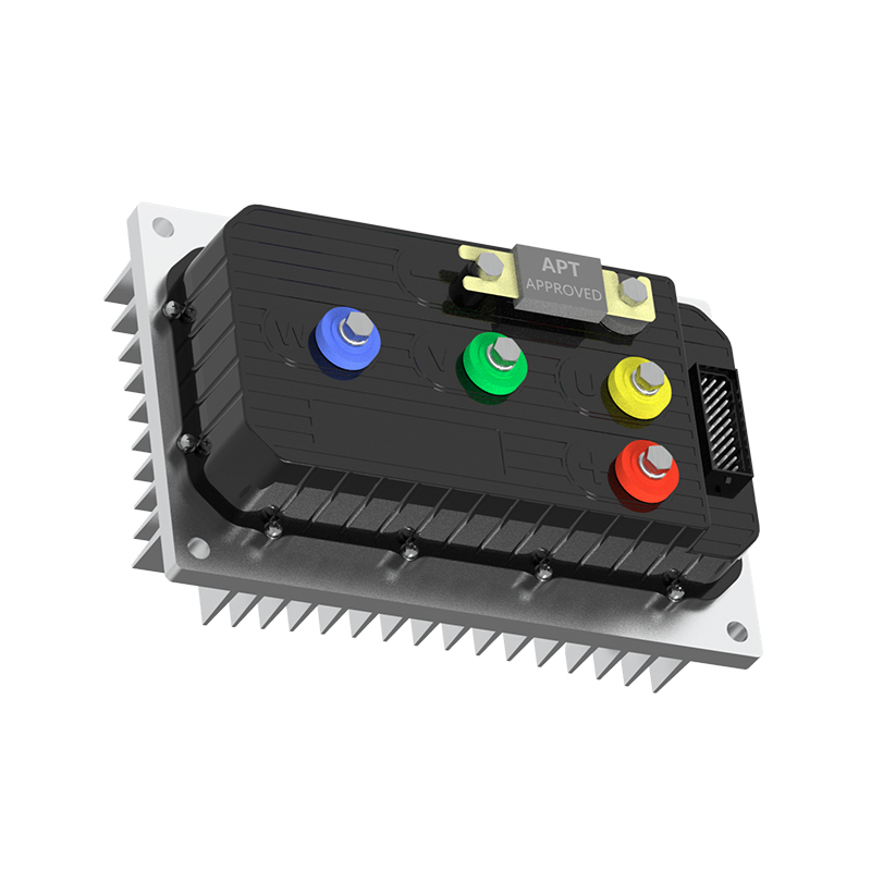
From Arduino Prototype to Production-Grade Motor Control
A PWM-driven ESC is the right tool for proving a concept — it's cheap, well-documented, and needs no configuration software. But it also has real limits: no current feedback to the Arduino, minimal protection logic, and a control resolution tied to a 1000-2000 microsecond pulse window that doesn't scale well once torque control, closed-loop speed regulation, or fault reporting become requirements.
When a project moves past prototyping toward a fielded product, the usual next step is a controller that communicates over a digital bus rather than a single PWM line. a UART-TTL debugging interface used to configure production motor controllers plays a role here similar to the Arduino serial monitor — it lets you read parameters and tune behavior directly rather than guessing from pulse widths alone.
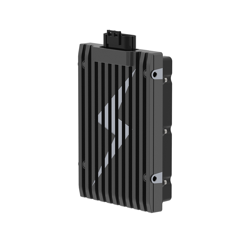
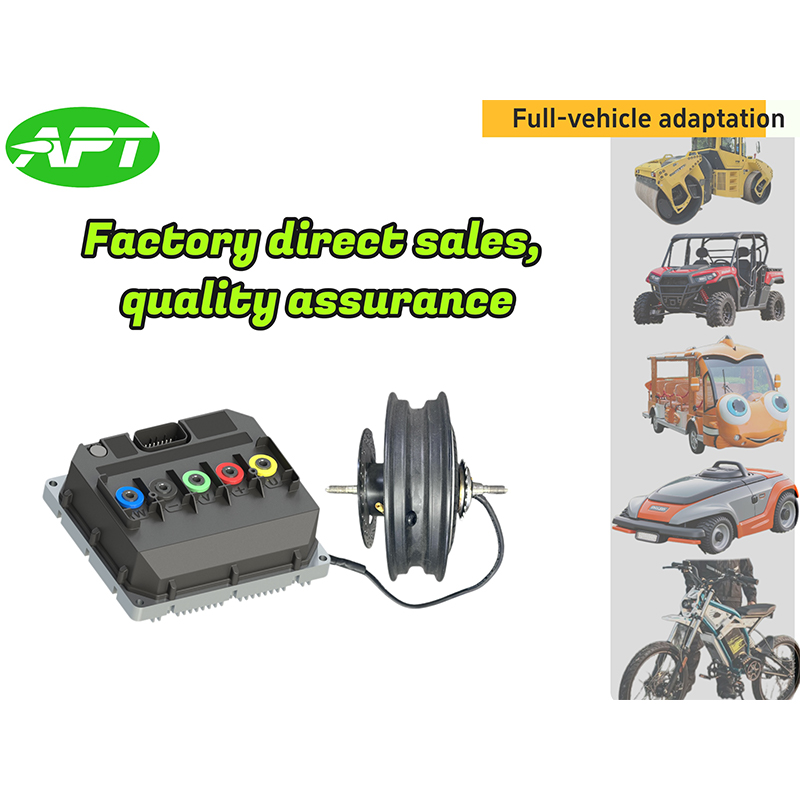
For teams outgrowing hobby ESCs, an entry point into APT's CAN bus-programmable BLDC motor controllers offers the kind of configurable current limiting and diagnostics that a basic ESC simply doesn't expose. Applications needing tighter response — robotics arms, actuated mechanisms, anything with a fast-changing load — are better served by a fast-response BLDC controller built for real-time closed-loop applications rather than an open-loop hobby ESC.
Since controller and motor specs need to align on voltage, current, and Hall sensor compatibility, it's worth reviewing controller and motor pairing guidance for matching drive electronics to motor specs before committing to hardware for a production run. It's also worth understanding how software layers are reshaping modern motor control, since firmware-level tuning is increasingly what separates a good production controller from a merely adequate one.
NEXT:Mid-Drive Motor E-Bikes: Benefits, Mechanics & Buying Guide
Interested in cooperation or have questions?
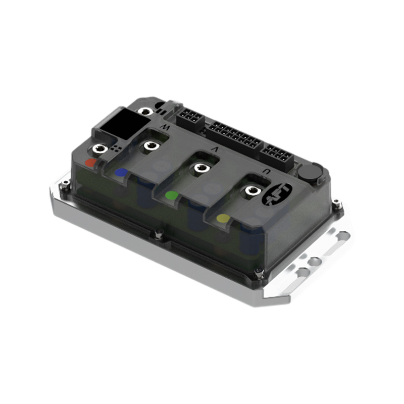
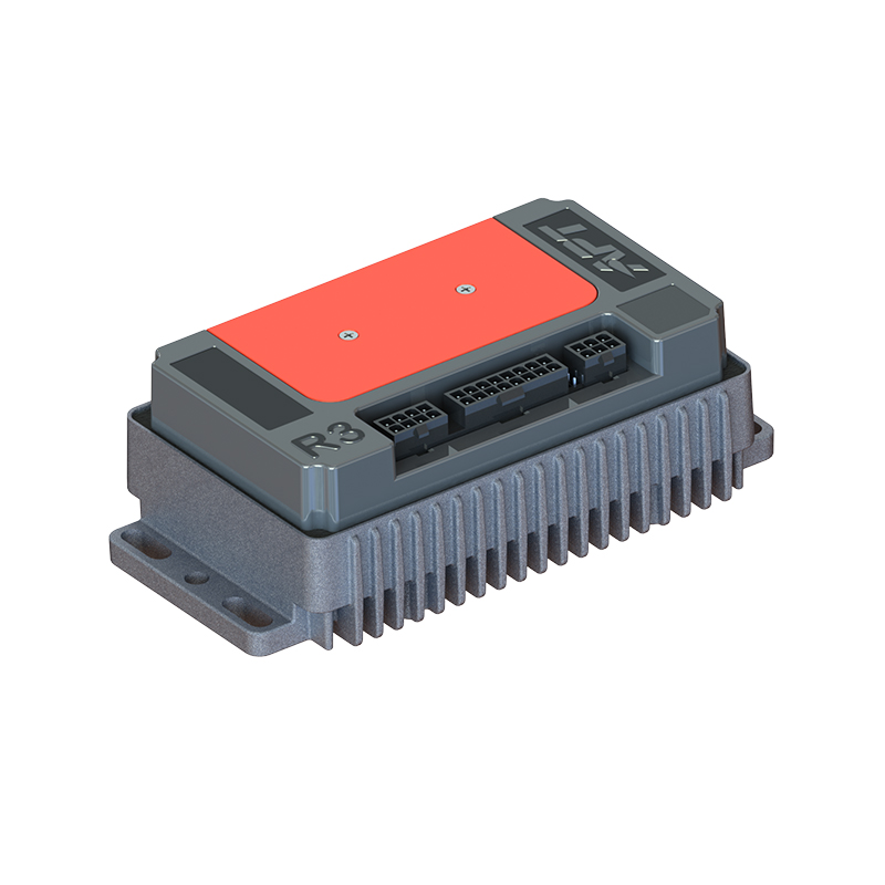
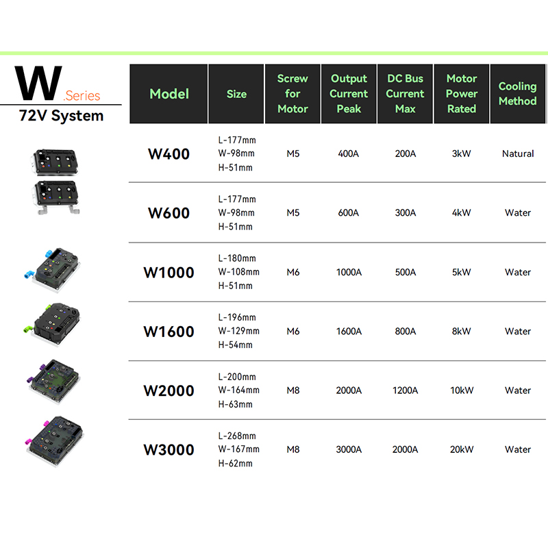


As Custom Permanent Magnet Synchronous Motor Controllers Manufacturers and Permanent Magnet Motor Controllers Suppliers in China, Focusing on the drive control of permanent magnet synchronous motors, we provide a safe and sufficient power source for the electrification of travel vehicles.
- [email protected]
- +86-170 9191 9800
- Room 123A, No. 1000 Ziyue Road, Minhang District, Shanghai, China
Copyright © Shanghai APT Power Technology Co., Ltd.All rights reserved

