 English
 Español
 عربى
عربى
BLDC Hall Sensor: How It Works, Types & Troubleshooting Guide
Content
What Is a Hall Sensor in a BLDC Motor
Pull the end cap off most brushless DC motors and you'll find three tiny components clustered near the windings, each barely larger than a grain of rice. Those are the Hall sensors, and without them — or a substitute like back-EMF sensing — the motor has no way of knowing which way to push.
A Hall sensor detects magnetic fields using the Hall effect: when a magnetic field passes perpendicular to a current-carrying element, it pushes charge carriers to one side, producing a measurable voltage. In a BLDC motor, three of these sensors sit on the stator near the non-driving end, positioned so the rotor's permanent magnets sweep past them as the shaft turns. Each sensor switches high or low depending on whether a north or south pole is nearby, and the combination of all three signals tells the controller exactly where the rotor sits at any instant — even when the motor isn't moving.
How Hall Sensors Drive Commutation
A three-phase BLDC motor needs its winding current switched in the correct sequence to keep the rotor turning — a process called commutation. Hall sensors make this possible by giving the controller a direct readout of rotor position, rather than forcing it to infer position indirectly.
With three sensors spaced around the stator, the rotor's magnets produce one of six possible high/low combinations as it passes through a full electrical revolution. Each combination corresponds to a specific 60° sector, and the controller uses a lookup table to decide which two of the three phases should be energized for that sector. As the rotor advances into the next sector, the Hall pattern changes, the controller switches to the next winding pair, and the rotating magnetic field keeps pulling the rotor forward — six discrete steps per electrical cycle, known as trapezoidal or six-step commutation.
This is also why Hall sensors matter most at standstill and low speed. A controller relying on back-EMF has nothing to read until the motor is already spinning fast enough to generate a usable signal; a Hall-equipped motor reports its position from the moment power is applied, which is why sensored designs start cleanly under load with no open-loop guessing.
Types of Hall Effect Sensors
Not all Hall sensors behave the same way, and the distinction matters when specifying or troubleshooting a motor.
- Digital unipolar sensors switch on when either magnetic pole passes nearby and switch off once the field drops away. They're simple and inexpensive but less common in BLDC commutation because they don't distinguish pole polarity as cleanly.
- Digital bipolar (latching) sensors switch on in the presence of one pole and switch off only when the opposite pole arrives — holding their state in between. This latching behavior gives clean, repeatable transitions and is the standard choice for BLDC commutation.
- Analog (linear) sensors output a voltage proportional to field strength rather than a simple on/off signal. They're used less often for basic commutation but show up in applications needing finer position resolution through interpolation.
Key Selection Criteria
Choosing a Hall sensor — or evaluating one already built into a motor — comes down to a handful of parameters that directly affect commutation accuracy and motor efficiency.
| Parameter | What It Affects |
|---|---|
| Sensitivity (BOP/BRP) | Lower switch points allow smaller magnets and more compact motor designs |
| Repeatability | Consistent switching timing preserves accurate torque delivery |
| Response time | Faster response supports higher commutation frequencies and motor speeds |
| Jitter | Lower jitter reduces angle error and speed variation at constant RPM |
| Operating voltage range | Must match the controller's logic level, typically 5V or 3.3V |
| Temperature stability | Determines reliability in motors that run hot under sustained load |
A deeper technical breakdown of these parameters, including how BOP and BRP values are read from a datasheet, is available in this Hall-effect sensor selection guide from Portescap.
Sensored vs Sensorless BLDC Control
Hall sensors aren't the only way to commutate a BLDC motor, and the alternative — sensorless, back-EMF-based control — trades one set of strengths for another.
Sensored motors deliver reliable starting torque under load, since position is known even at zero RPM, and they hold up well in applications with frequent starts, stops, or direction changes. The cost is extra wiring — typically a five-wire harness — and one more component that can fail from heat, vibration, or a bad connector. Sensorless control eliminates that wiring and the associated failure point entirely, but it can't determine rotor position until the motor is already turning fast enough to generate detectable back-EMF, which means an open-loop startup ramp before closed-loop control takes over.
For motors that run continuously at moderate-to-high speed — fans, pumps, drone propulsion — sensorless designs are often the more practical choice. For anything needing dependable torque from a standing start — direct-drive lifts, servo-style positioning, e-bike hub motors pulling away from a stop on a hill — Hall sensors remain the safer bet. This trade-off is explored in more depth in this comparison of sensorless versus Hall-effect sensored brushless motor control, and this overview of how BLDC motor controllers handle commutation more broadly.
Diagnosing Common Hall Sensor Faults
A motor that jerks, stalls on startup, or runs in only one direction before cutting out is showing classic symptoms of a Hall sensor problem rather than a winding fault.
- Missing signal on one channel: a single failed sensor produces an invalid state combination, which most controllers will flag as a fault rather than attempt to commutate incorrectly.
- Rough or jerky rotation at low speed: often points to a misaligned sensor or one that's drifted out of its correct angular position relative to the rotor magnets.
- Motor spins the wrong direction or stalls immediately: can indicate two Hall wires swapped during a repair, or a sensor wired to the wrong phase reference.
- Intermittent cutout under vibration: a strong sign of a cracked solder joint or a connector working loose rather than a failing sensor itself.
A multimeter on the sensor's 5V supply and ground pins confirms power is reaching the sensor board; checking each signal wire against ground while slowly rotating the shaft by hand should show clean transitions between high and low as each magnet pole passes. A signal that never changes, or that flickers erratically, points to that specific sensor or its wiring rather than the controller.
Matching Hall Sensor Output to Your Motor Controller
A Hall-equipped motor is only half the equation — the controller on the other end of that five-wire harness has to read the same logic levels and expect the same sensor arrangement.
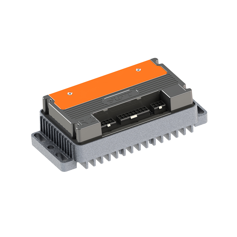
Before pairing a motor and controller, confirm the Hall supply voltage matches what the controller outputs — 5V and 3.3V logic aren't interchangeable without a level shifter — and that the controller's position sensor interface is configured for Hall input rather than encoder or resolver signals. Controllers that support multiple sensing methods offer flexibility here; the R2 series high-compatibility BLDC motor controller, for example, works with both Hall-effect sensored and sensorless motors, which simplifies swapping between motor types without changing hardware. For guidance on matching specific controller models to Hall-equipped motor specifications, this controller and motor pairing reference walks through the parameters that need to align. The full BLDC motor controller lineup covers a range of voltage and current classes for motors of different sizes.
NEXT:BLDC Motor with Arduino: Wiring, Code & Control Guide
Interested in cooperation or have questions?
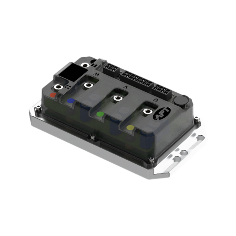
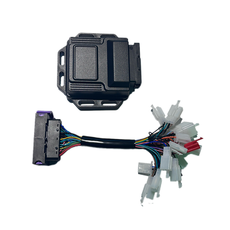
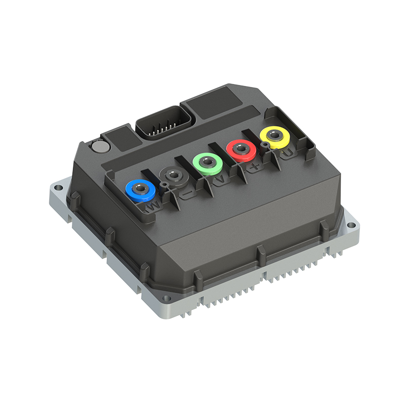


As Custom Permanent Magnet Synchronous Motor Controllers Manufacturers and Permanent Magnet Motor Controllers Suppliers in China, Focusing on the drive control of permanent magnet synchronous motors, we provide a safe and sufficient power source for the electrification of travel vehicles.
- [email protected]
- +86-170 9191 9800
- Room 123A, No. 1000 Ziyue Road, Minhang District, Shanghai, China
Copyright © Shanghai APT Power Technology Co., Ltd.All rights reserved

