 English
 Español
 عربى
عربى
Electromagnetic Induction Motors & AC Motors: How They Work
Electric motors are among the most consequential inventions in engineering history, and the principle that makes most of them work — electromagnetic induction — was established nearly two centuries ago. Today, that same principle powers everything from industrial compressors to electric bicycles. Understanding what AC motors are, how electromagnetic induction drives them, and how the technology has evolved into the brushless motors used in modern electric mobility gives a complete picture of one of engineering's most durable and adaptable ideas.
Content
- 1 What Is an AC Motor?
- 2 The Principle of Electromagnetic Induction
- 3 How a Rotating Magnetic Field Is Created
- 4 The Squirrel Cage Rotor and Slip
- 5 Induction Motors vs Synchronous Motors
- 6 Single-Phase vs Three-Phase Induction Motors
- 7 From AC Induction to Brushless DC: The Modern Evolution
- 8 Applications in Modern Electric Mobility
What Is an AC Motor?
An AC motor is an electric motor that converts alternating current (AC) electrical energy into mechanical rotational energy. Unlike direct current (DC) motors, which operate on a current that flows in one direction, AC motors run on current that periodically reverses direction — typically at 50 or 60 times per second depending on the power grid frequency of the region.
Every AC motor consists of two principal mechanical components. The stator is the stationary outer assembly, formed from a ring of electromagnet coils wound into a laminated steel core. When AC power flows through the stator windings, they produce a magnetic field. The rotor is the rotating inner assembly, positioned inside the stator's cylindrical cavity. The interaction between the stator's magnetic field and the rotor — achieved through electromagnetic induction, permanent magnets, or external excitation depending on motor type — generates the torque that drives the output shaft.
AC motors divide into two fundamental operating categories: induction (asynchronous) motors and synchronous motors. Induction motors are by far the more common type across industrial and commercial applications, accounting for the overwhelming majority of motors in use worldwide.
The Principle of Electromagnetic Induction
Electromagnetic induction is the foundation of how induction motors generate torque without any electrical connection to the rotor. The principle, established by Michael Faraday in 1831, states that a changing magnetic field passing through a conductor induces an electric current in that conductor. This induced current, in turn, produces its own magnetic field.
In an induction motor, the stator's AC-powered windings create a magnetic field that rotates continuously around the stator bore. This rotating field passes through the rotor conductors, inducing a current in them by Faraday's law. That induced current generates a secondary magnetic field in the rotor. By Lenz's law, this secondary field opposes the change that created it — meaning it tries to eliminate the relative motion between the rotating stator field and the stationary rotor by causing the rotor to rotate in the same direction as the stator field.
The result: the rotor spins, following the rotating magnetic field, without any physical electrical connection between stator and rotor. No brushes, no slip rings on the rotor side, no commutator — the energy transfer happens entirely through the changing magnetic field across the air gap. This is why induction motors are so mechanically simple, robust, and long-lived compared to brush-type motors: there are no contact components on the rotor to wear out.
How a Rotating Magnetic Field Is Created
The rotating magnetic field is the key mechanism that drives electromagnetic induction in an AC motor — and it is an emergent property of three-phase AC power. In a three-phase system, three separate AC voltages are supplied simultaneously to three sets of stator windings, each pair of windings physically offset from the others by 120 degrees around the stator bore. The three voltages are also electrically offset by 120 degrees — meaning they reach their peak values at different moments in each cycle.
As each phase reaches its peak, the electromagnets energized by that phase become strongest, pulling the effective magnetic field of the stator toward that set of poles. As the cycle progresses and the next phase peaks, the field shifts to the next set of poles — 120 degrees around the stator. The net effect of three sets of electromagnets peaking in sequence, spaced equally around the circumference, is a magnetic field that appears to rotate smoothly around the stator at a speed determined by the supply frequency and the number of magnetic poles in the stator winding.
This synchronous speed in revolutions per minute is given by: Ns = (120 × f) / P, where f is the supply frequency in Hz and P is the number of poles. A two-pole motor on a 50 Hz supply rotates at a synchronous speed of 3,000 RPM; a four-pole motor on the same supply rotates at 1,500 RPM. Single-phase motors can also produce a rotating field, but they require auxiliary starting windings or capacitors because a single-phase supply alone produces a pulsating rather than rotating field.
The Squirrel Cage Rotor and Slip
The most common rotor construction in AC induction motors is the squirrel cage rotor — named for its resemblance to the exercise wheel used by small animals. It consists of a series of aluminum or copper conductor bars embedded in slots in a laminated iron core, with the bars short-circuited at both ends by conducting end rings. There are no windings, no insulation, and no external electrical connections — the rotor is mechanically simple to manufacture and practically indestructible under normal operating conditions.
When the rotating magnetic field from the stator sweeps across these conductor bars, it induces currents that flow through the bars and around the end rings. These circulating currents produce the rotor's magnetic field, which interacts with the stator field to generate torque. The induced current — and therefore the torque — depends on the rate at which the stator field cuts across the rotor bars. If the rotor were to reach exactly the same speed as the rotating stator field (synchronous speed), there would be no relative motion, no field cutting, no induced current, and no torque. The rotor therefore always runs slightly slower than synchronous speed.
This speed difference is called slip, expressed as a percentage of synchronous speed. At no load, slip is very small — typically 0.5% to 1%. Under full rated load, slip increases to around 3% to 8% depending on motor design. Slip is not a deficiency; it is the necessary mechanism by which an induction motor generates torque. Without slip, there is no electromagnetic induction, and without electromagnetic induction, there is no torque.
Induction Motors vs Synchronous Motors
Synchronous motors represent the other main branch of AC motor design. Where an induction motor's rotor is driven entirely by electromagnetically induced currents, a synchronous motor's rotor is equipped with permanent magnets or separately excited electromagnets that lock the rotor to exactly the speed of the rotating stator field — with zero slip.
| Characteristic | Induction (Asynchronous) Motor | Synchronous Motor |
|---|---|---|
| Rotor excitation | Electromagnetically induced (no connection needed) | Permanent magnets or external DC excitation |
| Speed relative to supply | Always slightly below synchronous speed (slip) | Exactly synchronous speed (zero slip) |
| Starting behavior | Self-starting (three-phase); needs assistance (single-phase) | Not inherently self-starting without auxiliary means |
| Speed regulation | Varies slightly with load | Constant regardless of load |
| Typical application | Pumps, fans, compressors, general industry | Precision drives, clocks, generators, BLDC motors |
| Construction complexity | Simple, robust rotor | More complex, higher cost |
Synchronous motors are used where precise, constant speed is required regardless of load variation — in clocks, signal generators, and high-precision positioning drives. Induction motors dominate general industrial and commercial applications because of their lower cost, higher robustness, and self-starting capability in three-phase configurations.
Single-Phase vs Three-Phase Induction Motors
Three-phase induction motors are self-starting: the three-phase supply naturally produces a rotating magnetic field, which immediately begins inducing torque in the squirrel cage rotor as soon as power is applied. They are more efficient, produce higher power factor, and are used in virtually all industrial motor applications from small pumps to multi-megawatt drives.
Single-phase induction motors present a fundamental challenge: a single-phase AC supply produces a pulsating magnetic field, not a rotating one. A pulsating field can sustain rotation but cannot start it — the motor has no preferred direction of rotation and zero net starting torque when stationary. Several design strategies address this, each producing a distinct motor variant.
| Motor Type | Starting Method | Typical Application |
|---|---|---|
| Split-phase | Auxiliary winding with phase shift via resistance | Small appliances, fans, blowers |
| Capacitor-start | Capacitor in series with start winding; disconnected after starting | Compressors, pumps, power tools |
| Capacitor-run (PSC) | Permanent capacitor in run winding for continuous phase shift | HVAC fans, refrigerators, ceiling fans |
| Shaded pole | Copper shading ring creates phase-shifted flux in part of each pole | Very small loads: instrument fans, small appliances |
From AC Induction to Brushless DC: The Modern Evolution
The brushless DC (BLDC) motor — now the dominant motor type in electric bicycles, e-scooters, drones, and electric vehicle auxiliary drives — is not an AC induction motor in the traditional sense. Rather than relying on electromagnetically induced rotor currents, a BLDC motor uses permanent magnets on the rotor and electronically controlled current switching in the stator to produce rotation. In this respect it resembles a synchronous motor more closely than an induction motor.
The connection to AC motor principles lies in the stator: a BLDC motor's stator produces a rotating magnetic field through precisely timed switching of DC current through its windings — an effect functionally equivalent to what three-phase AC achieves through sinusoidal current variation. The motor controller performs the electronic commutation that replaces the brushes of a traditional DC motor, using rotor position feedback (from Hall effect sensors or back-EMF sensing) to energize the correct stator windings at each moment in the rotation cycle.
The result is a motor that combines the synchronous operation and high efficiency of a permanent magnet synchronous motor with the controllability and compactness demanded by battery-powered applications. BLDC motors eliminate the brush wear that limits the service life of traditional DC motors, operate efficiently across a wide speed range, and produce high torque density in a compact package — making them the engineering foundation of modern electric mobility.
Applications in Modern Electric Mobility
The principles of electromagnetic induction and rotating magnetic fields, developed in the nineteenth century, are directly embodied in the motors powering today's electric bicycles and light electric vehicles — albeit in their modern brushless permanent magnet form. Two distinct motor configurations dominate this market, each with different performance characteristics suited to different riding styles and requirements.
Hub motors integrate the motor directly into the wheel hub — front or rear — with the stator fixed to the axle and the rotor forming the outer shell that drives the wheel. The electromagnetic interaction between the fixed stator windings and the rotating permanent magnet rotor directly turns the wheel, with no mechanical power transmission chain between motor and wheel. This simplicity makes hub motors maintenance-friendly and quiet. Hub motors for electric bicycles and light electric vehicles suit commuter, cargo, and leisure applications where straightforward installation and low maintenance are priorities.
Mid-drive motors position the motor at the bicycle's bottom bracket, driving the crank and chain rather than the wheel directly. This arrangement lets the rider use the bicycle's existing gear system to multiply motor torque, making mid-drive systems significantly more efficient on hilly terrain and better matched to variable-load conditions. Mid-drive motors for high-performance electric bikes deliver the torque and terrain versatility demanded by mountain e-bikes, cargo bikes, and performance commuter applications.
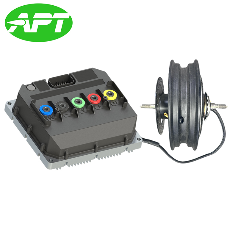
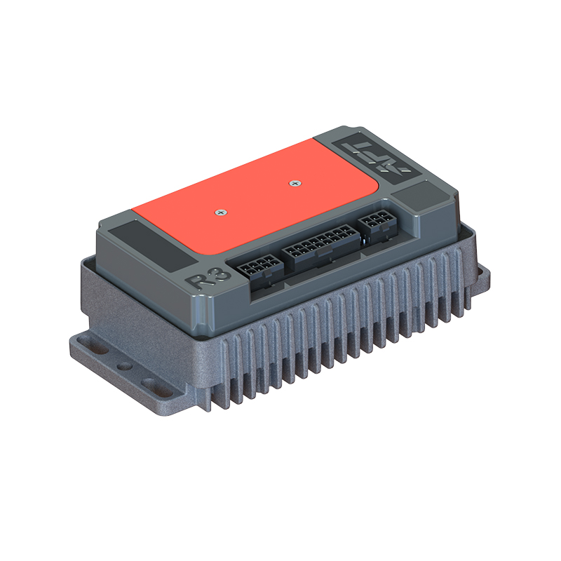
In both configurations, the motor cannot operate effectively without a matched motor controller. The controller performs the electronic commutation that replaces mechanical brushes, manages current delivery to the stator windings based on rotor position feedback, and translates rider input (throttle, pedal assist level) into precise torque output. Brushless DC motor controllers for hub and mid-drive systems are engineered to match specific motor winding configurations, voltage ranges, and communication protocols. For engineers and integrators building complete drive systems, the controller and motor pairing guide provides the specification-matching framework needed to select compatible controller and motor combinations for a given vehicle platform and performance target.
NEXT:Mid-drive Motor Guide: Efficiency, Torque & Maintenance
Interested in cooperation or have questions?

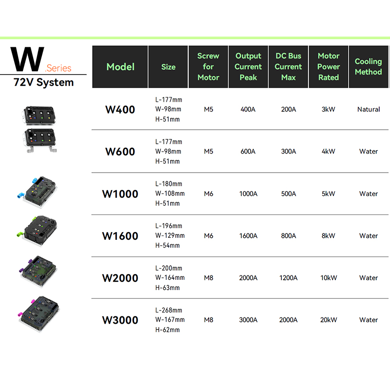

As Custom Permanent Magnet Synchronous Motor Controllers Manufacturers and Permanent Magnet Motor Controllers Suppliers in China, Focusing on the drive control of permanent magnet synchronous motors, we provide a safe and sufficient power source for the electrification of travel vehicles.
- [email protected]
- +86-170 9191 9800
- Room 123A, No. 1000 Ziyue Road, Minhang District, Shanghai, China
Copyright © Shanghai APT Power Technology Co., Ltd.All rights reserved

