 English
 Español
 عربى
عربىServo Motor Controllers: How They Work, Types & Selection Guide
A robot arm stops exactly where it should, 10,000 times a day, without drift. A CNC spindle accelerates to 12,000 RPM and holds it within a fraction of a percent. An e-bike motor delivers exactly the torque the rider demands on a steep climb, without surging or stuttering. None of this happens through mechanical luck. It happens because a servo motor controller is continuously reading the system state, comparing it to a target, and adjusting the output dozens of thousands of times per second. Understanding how that process works—and what separates a well-matched controller from the wrong one—is the foundation of any serious motion control decision.
Content
- 1 What Is a Servo Motor Controller?
- 2 Closed-Loop vs. Open-Loop: The Fundamental Difference
- 3 Core Control Algorithms: PID, FOC, and Beyond
- 4 Types of Servo Motor Controllers by Architecture
- 5 Key Specifications to Evaluate
- 6 Servo Controllers in E-Bike and Light EV Applications
- 7 Matching Controller to Motor: The Critical Step
What Is a Servo Motor Controller?
A servo motor controller is an electronic device that regulates the operation of a servo motor by continuously adjusting its output based on real-time feedback. Unlike a simple open-loop driver that sends a fixed command and hopes the motor follows, a servo controller closes the loop: it reads the motor's actual position, speed, or torque from a sensor, compares that value to the desired setpoint, calculates the error, and generates a corrective output signal to minimize that error.
This feedback architecture is what defines servo control. The word "servo" derives from the Latin servus (servant)—the controller serves the command, continuously adjusting to make reality match the instruction. The result is precise, repeatable, and disturbance-resistant motion that open-loop systems cannot achieve: a servo system automatically compensates for load changes, voltage fluctuations, and motor parameter variation without any external intervention.
Modern servo controllers for brushless DC (BLDC) and permanent magnet synchronous motors (PMSM) are sophisticated digital systems. They run control algorithms at switching frequencies of 10 kHz to 100 kHz or higher, execute real-time feedback calculations in microseconds, and communicate with higher-level systems through industrial protocols. The hardware at the core is typically a dedicated microcontroller or DSP (digital signal processor) matched to the computational demands of the control algorithm being implemented.
Closed-Loop vs. Open-Loop: The Fundamental Difference
The distinction between open-loop and closed-loop control is the single most important concept in understanding why servo controllers behave as they do.
In an open-loop system, the controller sends a command—a voltage level, a PWM duty cycle, a step pulse—and the motor responds as best it can. There is no mechanism for the system to detect or correct for errors. If the load increases and the motor slows down, the controller doesn't know. If the motor misses a step, the position error accumulates invisibly. Open-loop control works in benign, well-characterized conditions where load variations are minimal and absolute position accuracy is not required. Stepper motors in light-duty applications are the most common example.
In a closed-loop servo system, the motor's actual state is continuously measured—usually by a Hall effect sensor, optical encoder, or resolver—and fed back to the controller. The controller calculates the difference between the commanded state and the actual state (the error), and drives the motor to reduce that error. This architecture handles variable loads, disturbances, and motor parameter drift automatically. Applications requiring tight control of position, speed, or torque under varying conditions—industrial automation, robotics, CNC machining, electric vehicles, aerospace actuators—invariably use closed-loop servo control.
Core Control Algorithms: PID, FOC, and Beyond
The algorithm executing inside a servo controller determines how it converts feedback error into output commands. Several control architectures dominate in practice:
- PID control (Proportional-Integral-Derivative): The foundational algorithm in servo control. The proportional term generates output proportional to the current error; the integral term eliminates steady-state error by accumulating the error over time; the derivative term provides damping by responding to the rate of change of error. PID is computationally simple, well-understood, and effective across a wide range of applications. Most industrial servo drives implement PID at the speed and position loop level, with the derivative gain tuned to prevent oscillation under dynamic load changes.
- Field-Oriented Control (FOC): The current standard for high-performance BLDC and PMSM control. FOC transforms the three-phase motor currents into a rotating reference frame (the d-q frame) aligned with the rotor's magnetic field, using Clarke and Park transformations. In this frame, torque and flux can be controlled independently with two separate PID loops—one for the torque-producing current (q-axis) and one for the flux-producing current (d-axis). The result is smooth, low-ripple torque output, high efficiency across the speed range, and precise dynamic response. IEEE research on FOC implementation for BLDC motors confirms that FOC enables independent control of torque and flux components, optimizing motor dynamic performance with low torque ripple and high energy efficiency—advantages that are particularly significant in e-bike, robotics, and precision drive applications.
- Six-step (trapezoidal) commutation: A simpler commutation method for BLDC motors that switches the three motor phases in a fixed sequence based on rotor position from Hall sensors. Easier to implement than FOC, with lower computational requirements, but produces more torque ripple and is less efficient—particularly at low speeds. Suitable for cost-sensitive or lower-performance applications where the smoothness of FOC is not required.
- Cascade control (multi-loop): Industrial servo systems typically implement three nested control loops: an outer position loop, a middle velocity loop, and an inner current (torque) loop. Each loop operates at a higher bandwidth than the one outside it. The position loop commands a velocity setpoint; the velocity loop commands a current setpoint; the current loop directly controls motor torque. This structure provides fast dynamic response while maintaining steady-state accuracy at all operating points.
Types of Servo Motor Controllers by Architecture
Servo controllers are available in several physical and functional configurations, matched to different application requirements:
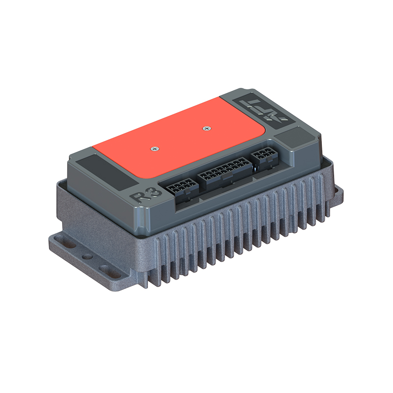
- Single-axis standalone controllers: Self-contained units that manage one motor channel. The most common configuration for dedicated machine axes, pump drives, and standalone automation tasks. These controllers accept a command input (analog voltage, PWM signal, or digital protocol), close the feedback loop internally, and output the drive signal to the motor phases. Compact form factors are essential where installation space is constrained—particularly in e-bike systems and light EV applications where the controller must mount compactly near the motor or battery.
- Multi-axis controllers: A single controller managing two or more motor axes with synchronized motion. Essential for applications requiring coordinated motion between axes—robotic arms, gantry systems, multi-axis CNC machines, and automated assembly equipment where the motion profile of one axis must track or synchronize with another.
- Modular/distributed architectures: Drive intelligence is distributed, with individual axis amplifiers located near the motors and a central controller managing the overall motion program. Reduces wiring complexity and improves noise immunity by shortening the high-current motor cables. Common in large machine tools and factory automation installations.
- Integrated motor-controller units: The controller electronics are packaged directly with the motor, eliminating the separate controller enclosure and long cable runs. Reduces system complexity and improves reliability in space-constrained or harsh-environment applications. Hub motor and mid-drive systems for electric bicycles and light EVs frequently use this integrated approach. B2B brushless DC motor controllers for OEM and industrial drive integration span a range of architectures from standalone compact units to configurable high-current designs suited to volume manufacturing programs.
Key Specifications to Evaluate
Controller datasheets contain a dense set of parameters. The ones that most directly determine whether a controller suits a given application:
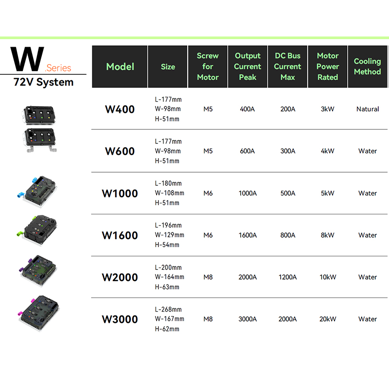
- Voltage range: Must match the system battery or supply voltage with appropriate margin. A controller rated for 24–72V nominal is typical for e-bike and light EV applications; industrial drives may require 200–480V AC input with internal rectification.
- Continuous and peak current rating: Continuous current defines the sustained load the controller can handle without thermal shutdown. Peak current—available for acceleration and short load spikes—may be two to three times the continuous rating. Undersizing the continuous current rating leads to thermal derating and premature failure in high-duty-cycle applications.
- Control algorithm and commutation method: FOC-based controllers deliver significantly smoother operation, higher efficiency, and better low-speed torque than six-step commutation alternatives. For applications where rider feel, acoustic noise, or energy efficiency is a priority, FOC is the correct choice.
- Switching frequency: Higher switching frequencies reduce current ripple and motor heating but increase controller switching losses. The optimum is application-dependent; most modern BLDC controllers operate at 16–32 kHz, placing switching noise above the audible range.
- Communication interface: CAN bus is standard for automotive and e-vehicle systems. RS-485, UART, and proprietary protocols are common in e-bike controllers for configuration and telemetry. Industrial drives typically support EtherCAT, Profibus, CANopen, or MODBUS depending on the automation platform.
- Protection features: Over-current, over-voltage, under-voltage, over-temperature, and phase-loss protection are baseline requirements. Controllers intended for outdoor or vehicular environments should specify the protection IP rating (ingress protection against dust and moisture).
For applications where selecting the right controller-motor combination is not straightforward, a controller and motor pairing scheme guide helps navigate compatibility between controller current ratings, motor KV values, pole counts, and Hall sensor configurations—avoiding the mismatches that cause poor performance or premature failure.
Servo Controllers in E-Bike and Light EV Applications
Electric bicycles and light electric vehicles represent one of the fastest-growing application segments for servo motor controllers. The requirements are specific: compact form factor, high efficiency across a wide speed range, smooth low-speed torque for rider comfort, and robust protection for outdoor operating conditions.
Two motor architectures dominate this segment, each with distinct controller implications:
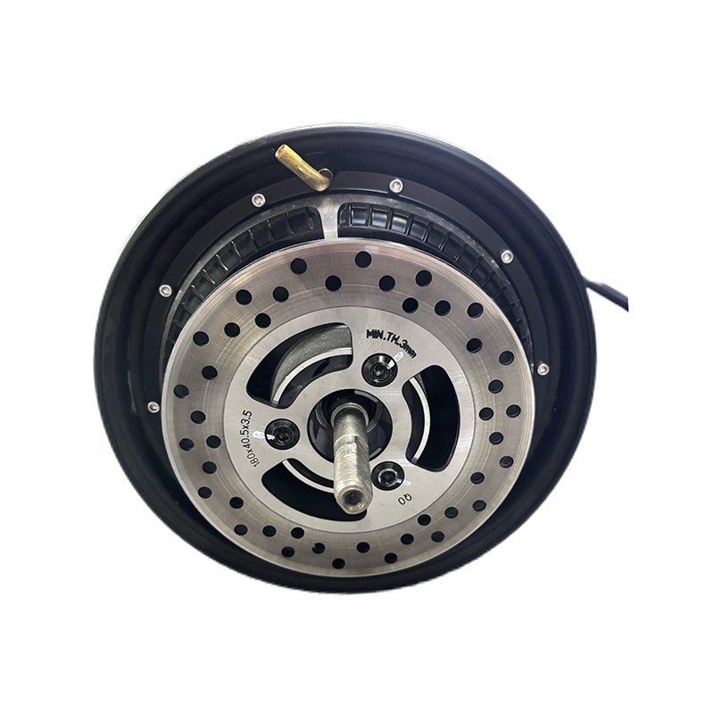
- Hub motors place the motor directly in the wheel hub. The controller must manage a motor with a relatively high pole count—often 20 poles or more—operating at low mechanical speed and high electrical frequency. Hub motors for direct-drive e-bike and light vehicle applications require controllers with fast commutation timing and accurate Hall sensor decoding to maintain smooth torque at low wheel speeds.
- Mid-drive motors drive the bicycle's bottom bracket, using the bike's drivetrain for mechanical advantage. The motor operates at higher RPM through the transmission, allowing a smaller, lighter motor to deliver high wheel torque through gear reduction. Mid-drive motors matched to high-efficiency BLDC controllers deliver superior hill-climbing performance and battery efficiency compared to direct-drive hub systems in terrain-variable riding conditions.
Controller selection for e-bike applications must also address the regulatory environment. Maximum continuous power output, peak assist levels, and speed limits vary by jurisdiction and affect controller programming requirements. Configurable current limits, PAS (pedal assist sensor) integration, and throttle response curves are practical software features that determine how closely the system meets both regulatory requirements and rider expectations.
For consumer-facing e-bike and personal EV products, B2C motor controllers designed for retail and direct-to-consumer e-mobility applications balance ease of installation with the performance characteristics—smooth torque delivery, efficient regenerative braking support, and configurable assist levels—that define the rider experience.
Matching Controller to Motor: The Critical Step
A servo motor and its controller form a system. Specifying them independently, then hoping they work together, is a common and costly mistake. The key compatibility parameters:
- Voltage and current matching: The controller's voltage range must cover the motor's rated operating voltage. The controller's current rating must exceed the motor's peak current draw under maximum load. Under-rated controllers thermal-limit or fail; over-rated controllers add unnecessary cost and size.
- Motor type and pole count: Sensorless FOC controllers require specific motor parameter inputs (phase resistance, inductance, back-EMF constant) for the observer algorithms to function correctly. Hall-sensor controllers must match the sensor wiring convention—different manufacturers use different Hall sensor sequences, and a mismatch produces erratic commutation.
- KV rating and application speed range: Motor KV (RPM per volt) determines the operating speed at a given supply voltage. A high-KV motor on a low-voltage controller never reaches its efficiency optimum; a low-KV motor on a high-voltage controller over-speeds. Matching KV to the application's speed and torque requirements—accounting for gear ratios where applicable—is the starting point of any drive system specification.
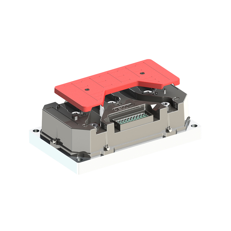
- Thermal management: Both motor and controller generate heat proportional to current and switching losses. A controller with adequate current rating but insufficient thermal dissipation will derate in sustained high-power operation. Verify that the controller's thermal design—heatsink area, thermal interface, ambient temperature rating—matches the duty cycle and environment of the application. For high-performance drive configurations, T-series high-performance motor controllers are engineered for demanding continuous-duty applications where thermal management and peak current capability are primary design constraints.
Servo motor controllers are not commodity components. The difference between a correctly specified controller and one that merely powers the motor shows up in efficiency, acoustic noise, dynamic response, service life, and ultimately in the performance of whatever the motor is moving. Getting the specification right—algorithm, architecture, ratings, and compatibility—is the work that separates reliable motion control systems from troublesome ones.
NEXT:AC Electric Motor Controller: Types, Technologies & Selection Guide
Interested in cooperation or have questions?
As Custom Permanent Magnet Synchronous Motor Controllers Manufacturers and Permanent Magnet Motor Controllers Suppliers in China, Focusing on the drive control of permanent magnet synchronous motors, we provide a safe and sufficient power source for the electrification of travel vehicles.
- [email protected]
- +86-170 9191 9800
- Room 123A, No. 1000 Ziyue Road, Minhang District, Shanghai, China
Copyright © Shanghai APT Power Technology Co., Ltd.All rights reserved
