 English
 Español
 عربى
عربى
Torque Motor Controller: Types, Control Methods & Selection Guide
Content
What a Torque Motor Controller Actually Does
Speed and position often get the most attention in motor control discussions, but torque is the foundational variable — the one that determines how much rotational force a motor delivers to its load at any given moment. A torque motor controller is the hardware and software system responsible for regulating that force output, ensuring the motor produces exactly the torque the application demands, whether that means holding a constant level under varying load, tracking a dynamic reference signal in milliseconds, or limiting output to protect downstream mechanical components.
The distinction between torque control and speed control is worth stating clearly. A speed controller tries to maintain a target rotational speed, adjusting current as loads vary. A torque controller does the opposite: it sets the rotational force directly, letting speed vary as the mechanical system dictates. In many real-world systems — electric vehicles, robotics, winding machines, traction drives — torque control is the inner loop that a speed or position controller sits on top of. The quality of the torque loop determines the responsiveness of everything above it.
Modern torque motor controllers are built around brushless DC (BLDC) and permanent magnet synchronous motor (PMSM) architectures, which allow precise current-based torque regulation through sophisticated control algorithms. The choice of control method — and the hardware that implements it — has a direct impact on efficiency, noise, dynamic response, and system reliability.
Core Control Methods: FOC, DTC, and Sensorless Approaches
Three control methods dominate modern torque motor controller design. Each represents a different engineering trade-off between precision, computational complexity, hardware requirements, and cost.
Field-Oriented Control (FOC), also called vector control, is the current benchmark for high-performance torque regulation. The principle is to decompose the stator current into two mathematically independent components: a flux-producing component (d-axis) and a torque-producing component (q-axis). By controlling these two components independently in a rotating reference frame synchronized to the rotor, the controller achieves the same precise, decoupled torque control over an AC motor that a simple DC motor with brush commutation provides naturally. The result is smooth, low-ripple torque output across the full speed range, high efficiency, and fast dynamic response. FOC requires real-time knowledge of rotor position — typically from a hall sensor, encoder, or resolver — and sufficient processing power to run the transformation mathematics at the PWM update rate. For BLDC and PMSM motors in demanding applications including electric vehicles, CNC drives, and robotics, FOC is the standard implementation.
Direct Torque Control (DTC) takes a fundamentally different approach. Rather than computing voltage vectors through a reference frame transformation, DTC selects switching states for the inverter directly based on the instantaneous error between measured and target torque and flux values. This eliminates the inner current control loop and the coordinate transformations that FOC requires, resulting in very fast torque response — switching decisions occur every few microseconds. The trade-off is higher torque ripple and more complex switching behavior compared to FOC. DTC is most commonly found in high-power industrial drive applications where response time is the primary criterion.
Sensorless control is not a distinct control algorithm but rather a technique that eliminates the physical rotor position sensor by estimating rotor angle from measured motor currents and voltages. At medium to high speeds, back-EMF estimation provides accurate rotor position tracking. At low speeds — where back-EMF is too small to measure reliably — more sophisticated observers (extended Kalman filters, sliding-mode observers) are required. Sensorless implementations reduce system cost, eliminate a potential point of failure, and simplify installation, at the cost of reduced accuracy and performance at very low speeds. Many modern BLDC motor controllers offer sensorless operation as an option alongside sensor-based modes, allowing the system to be configured for the application's speed range and accuracy requirements.
| Method | Torque Ripple | Dynamic Response | Sensor Requirement | Computational Load | Typical Application |
|---|---|---|---|---|---|
| FOC (Vector Control) | Low | Fast | Position sensor (or sensorless) | High | EV drives, robotics, CNC, servo |
| DTC | Higher | Very Fast | Current + voltage sensors | Medium | High-power industrial drives |
| Sensorless FOC | Low–Medium | Fast (mid/high speed) | None (estimated) | Very High | Cost-sensitive drives, e-bikes, scooters |
| Voltage-Mode Torque | Medium | Moderate | Minimal | Low | Simple BLDC, low-cost applications |
Controller Architecture: Hardware That Makes Torque Control Work
Understanding the control algorithm is only part of the picture. The hardware architecture of the controller determines whether the algorithm can execute at the required speed and whether the resulting drive signals actually produce clean, efficient motor output.
The power stage — typically a three-phase MOSFET or IGBT inverter bridge — converts the controller's PWM switching commands into the phase voltages and currents that drive the motor. Switching frequency, dead-time compensation, and gate drive design all affect torque ripple, efficiency, and electromagnetic noise. Higher switching frequencies reduce current ripple and improve torque smoothness but increase switching losses; the optimal frequency depends on the motor inductance, the heat dissipation capability of the controller, and the noise requirements of the application.
Current sensing is the feedback signal that closes the torque control loop. Shunt resistors in the motor phase lines or DC bus provide the raw measurement; the controller's analog-to-digital converters sample these at each PWM cycle to feed the current control loop. The accuracy, sampling rate, and noise rejection of the current sensing path directly determine how precisely the controller can regulate torque. For FOC implementations, current sensing quality is the single largest hardware factor affecting torque control performance.
Communication and programmability distinguish modern torque controllers from older fixed-function drives. CAN bus, RS-485, UART, and SPI interfaces allow the torque reference to be commanded dynamically from a supervisory controller, enabling the motor controller to function as a torque actuator within a larger motion control system. Parameter configurability — including current limits, PWM frequency, PI gains, and protection thresholds — allows the same controller hardware to be tuned for different motor types and application profiles.
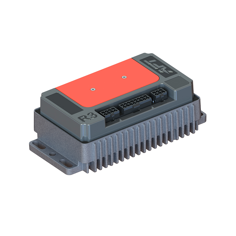
APT's brushless DC motor controllers for industrial and mobility applications implement FOC-based torque control with configurable operating modes, covering the full range from compact sensorless drives to high-performance sensored configurations. The T-series high-performance PMSM motor controllers extend this to permanent magnet synchronous motor platforms where maximum torque density and dynamic response are required.
Motor Types and Their Torque Control Requirements
The torque controller specification cannot be separated from the motor it drives. BLDC and PMSM motors share many control characteristics but differ in rotor construction and back-EMF waveform in ways that influence controller design. Hub motors and mid-drive motors — both common in e-mobility applications — present distinct torque control challenges that reflect their mechanical roles in the drivetrain.
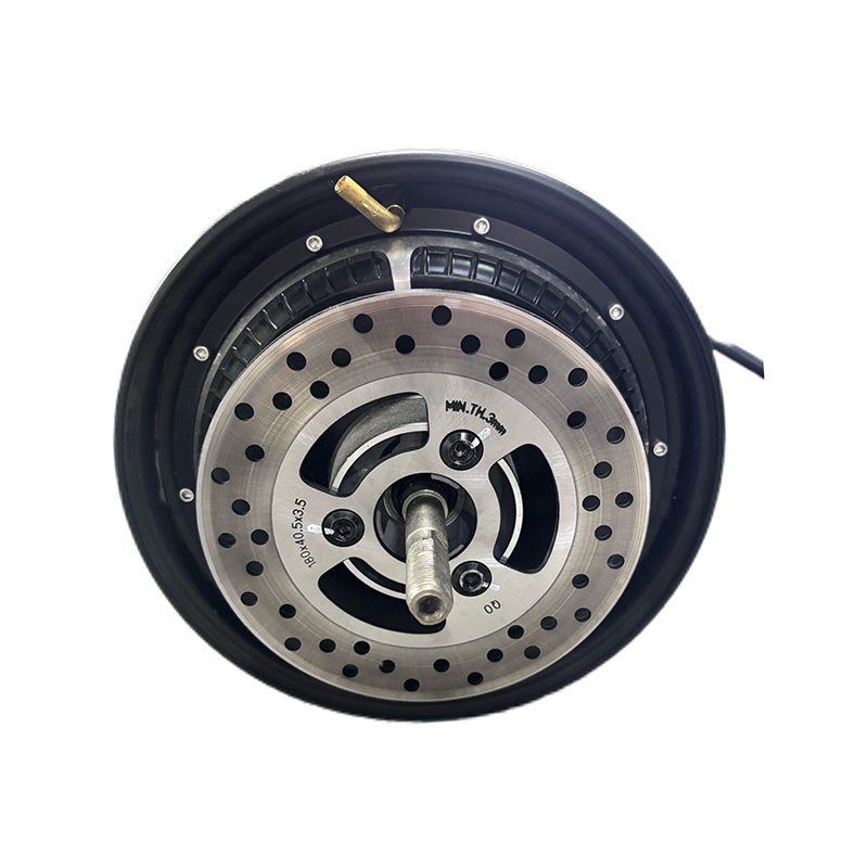
Hub motors integrate the motor directly into the wheel hub. Torque control of a hub motor is essentially direct torque delivery to the road surface, with no intermediate mechanical reduction. This demands high low-speed torque output and precise torque modulation for rider feel and traction management. Hall sensors in the hub provide rotor position for the FOC loop, though sensorless implementations are increasingly viable as observer algorithms improve. APT's electric hub motors designed for wheel-integrated drive systems are engineered for this direct-drive torque delivery profile.
Mid-drive motors connect to the drivetrain through the bicycle's or vehicle's existing transmission. The motor operates at higher speed, through a gear reduction, which means the torque control loop manages a different operating range than a hub motor. Mid-drive configurations allow the motor to operate closer to its peak efficiency point regardless of vehicle speed, with the transmission handling the ratio adaptation. This makes torque control strategy — particularly partial-load efficiency and regenerative torque management — more influential on system-level energy consumption. APT's mid-drive motors for high-efficiency transmission-coupled applications address this operating profile with motor designs optimized for the RPM range and torque characteristics of mid-drive duty cycles.
Industry technical resources, including detailed technical guidance on motor torque control methods covering FOC, DTC, PID, and sensorless implementations, consistently identify controller-motor matching as the primary determinant of real-world torque control quality — a point that applies equally to hub motor and mid-drive configurations.
Selecting the Right Torque Motor Controller
Controller selection reduces to five variables: voltage and current rating, control algorithm support, communication interface, motor compatibility, and application environment. Getting any one of these wrong results in a system that either underperforms or fails prematurely.
Voltage and current ratings must cover both the nominal operating point and the peak demand during acceleration and overload conditions. A controller specified only to the motor's continuous current rating will trip on protection during normal dynamic operation. The standard approach is to specify continuous current at the motor's rated operating point and verify peak current capability against the motor's locked-rotor or stall current, then apply an appropriate derating for thermal environment.
Control algorithm support determines achievable torque performance. If the application requires smooth torque at low speed — as in a direct-drive hub motor or a precision industrial actuator — FOC with current sensing is required. If cost and simplicity are the primary constraints and low-speed performance is not critical, sensorless voltage-mode control may be adequate. The controller's configurable parameter set determines how well a given hardware platform can be adapted to different motor types without hardware changes.
For system integrators sourcing motor and controller as a matched set, APT's controller and motor pairing scheme covering application-specific matching recommendations provides a structured framework for aligning controller specifications to motor electrical parameters and application duty cycle requirements — eliminating the most common source of torque control system failures before commissioning.
NEXT:Servo Motor Controllers: How They Work, Types & Selection Guide
Interested in cooperation or have questions?
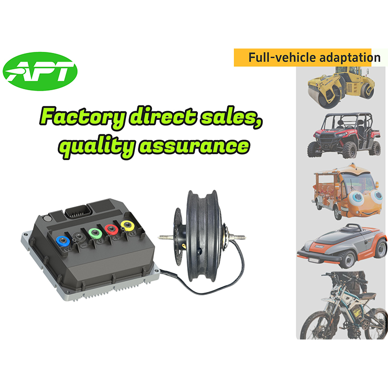
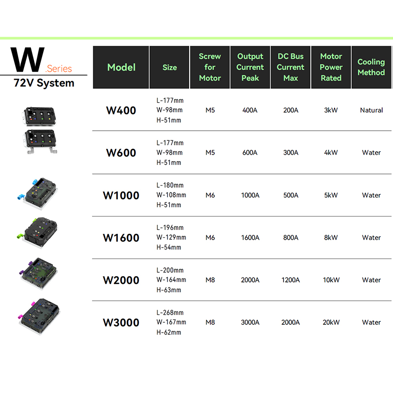
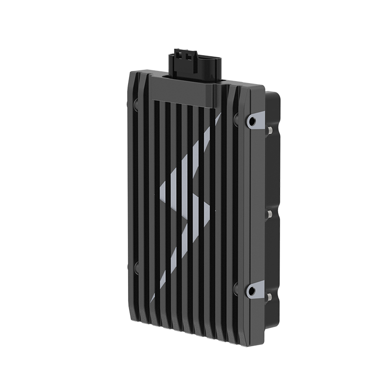
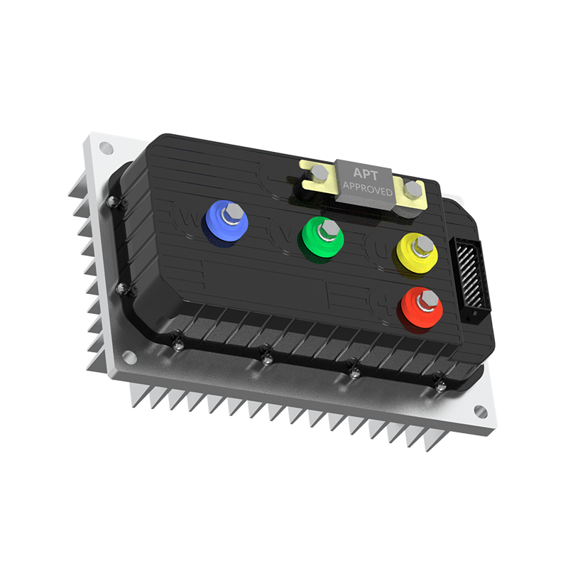

As Custom Permanent Magnet Synchronous Motor Controllers Manufacturers and Permanent Magnet Motor Controllers Suppliers in China, Focusing on the drive control of permanent magnet synchronous motors, we provide a safe and sufficient power source for the electrification of travel vehicles.
- [email protected]
- +86-170 9191 9800
- Room 123A, No. 1000 Ziyue Road, Minhang District, Shanghai, China
Copyright © Shanghai APT Power Technology Co., Ltd.All rights reserved

