 English
 Español
 عربى
عربىElectric Bike Controller: How It Works, Types & Selection
Content
- 1 The Electric Bike Controller: The Brain Behind Every E-Bike
- 2 What an Electric Bike Controller Actually Does
- 3 Types of E-Bike Controllers
- 4 Key Specifications Explained
- 5 Compatibility: Matching Controller to Motor, Battery, and Sensors
- 6 Popular E-Bike Controller Platforms and Their Characteristics
- 7 Programmable Controller Settings and What They Control
- 8 Diagnosing and Replacing a Faulty E-Bike Controller
- 9 Upgrading Your Controller for More Performance
The Electric Bike Controller: The Brain Behind Every E-Bike
The electric bike controller is the central electronic unit that regulates power flow between the battery and the motor. It determines how much current reaches the motor at any given moment, interprets signals from the throttle, pedal assist sensor, and brakes, and protects the entire electrical system from overcurrent, overvoltage, and overheating. While the battery provides energy and the motor converts it into motion, the controller is the component that makes the ride feel smooth, responsive, and safe.
Most riders rarely think about their e-bike controller until something goes wrong — a jerky throttle response, a motor that cuts out mid-ride, or a bike that simply won't start. Understanding what the controller does, how it is specified, and how to select or replace one correctly prevents those problems and allows meaningful performance upgrades when desired. This guide covers controller operation, types, specifications, compatibility, and replacement in practical detail.
What an Electric Bike Controller Actually Does
At its core, the e-bike controller is a power electronics device that converts DC battery voltage into a controlled current waveform driving the motor. For brushless DC (BLDC) motors — the type used in virtually all modern e-bikes — the controller must also commutate the motor: switching current through the three motor phase windings in a precise sequence to create continuous rotation.
Motor Commutation and Phase Control
A brushless hub motor or mid-drive motor has three sets of stator windings (phases) and a rotor with permanent magnets. The controller energizes each phase in turn, timed to the rotor's angular position, to pull and push the rotor continuously. Position sensing is typically provided by three Hall effect sensors inside the motor spaced 120° apart, which send signals to the controller 6 times per electrical revolution. Without correct commutation timing, the motor produces reduced torque, overheats, or refuses to turn. This is why motor and controller compatibility — specifically the Hall sensor signal voltage and commutation sequence — is non-negotiable.
PWM Speed and Torque Regulation
The controller regulates motor speed and torque using Pulse Width Modulation (PWM) — rapidly switching the MOSFETs (power transistors) on and off to vary the average voltage delivered to the motor windings. A typical e-bike controller switches at 15–20 kHz, fast enough that the motor inductance smooths the current into a near-continuous waveform. Higher PWM frequencies produce quieter, smoother motor operation at the cost of slightly higher switching losses in the MOSFETs. The throttle or pedal assist sensor provides a 0–5V or 1–4V analog signal that the controller uses as the torque/speed setpoint for this PWM regulation loop.
Protection Functions
A well-designed controller protects itself, the motor, and the battery through several built-in protection circuits:
- Overcurrent protection: Limits phase current to the rated maximum, preventing MOSFET burnout during stall or hard acceleration.
- Low voltage cutoff (LVC): Disconnects the motor when battery voltage drops below a set threshold — typically 2.5–3.0V per cell — protecting lithium cells from deep discharge damage.
- Overvoltage protection: Prevents damage from regenerative braking voltage spikes or charger malfunctions.
- Thermal protection: Reduces power output or cuts off entirely when the controller's internal temperature exceeds safe limits — usually 80–100°C on the MOSFET heatsink.
- Brake cutoff: Immediately reduces motor output to zero when a brake lever sensor is activated, preventing simultaneous motor drive and braking.
Types of E-Bike Controllers
E-bike controllers are categorized by their control algorithm, physical format, and the motor type they support. Choosing the right category is the first step in any replacement or upgrade decision.
Square Wave vs. Sine Wave Controllers
This is the most functionally significant distinction in e-bike controllers. A square wave controller switches the phase currents in a simple on/off pattern, commutating six times per electrical revolution. The result is efficient power delivery but a somewhat rough torque characteristic — particularly noticeable at low speeds and during startup. Square wave controllers are less expensive, generate less heat in the control circuitry, and are the dominant type in budget to mid-range e-bikes.
A sine wave controller generates a smoothly varying, sinusoidal current waveform in each phase, continuously adjusting the current based on the precise rotor angle (often using field-oriented control, FOC). This produces noticeably smoother acceleration, quieter motor operation, and better low-speed torque. Sine wave controllers typically deliver 5–15% greater efficiency at partial loads compared to equivalent square wave designs, which translates to meaningfully longer range. They cost more and require more sophisticated microcontroller firmware, but are standard on quality mid-drive systems and premium hub motor builds.
Hub Motor Controllers vs. Mid-Drive Controllers
Hub motor controllers are designed for the relatively straightforward commutation requirements of large, slow-spinning hub motors. They prioritize current capacity over control precision. Mid-drive controllers — such as those in Bosch, Shimano Steps, and Bafang BBS systems — are tightly integrated with the motor unit, incorporate torque sensor input for natural pedal-feel assistance, and communicate with the display and battery management system over a proprietary CAN bus or UART protocol. Mid-drive controllers are almost never interchangeable between brands and are not user-replaceable in most cases without brand-specific diagnostic tools.
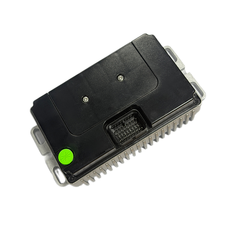
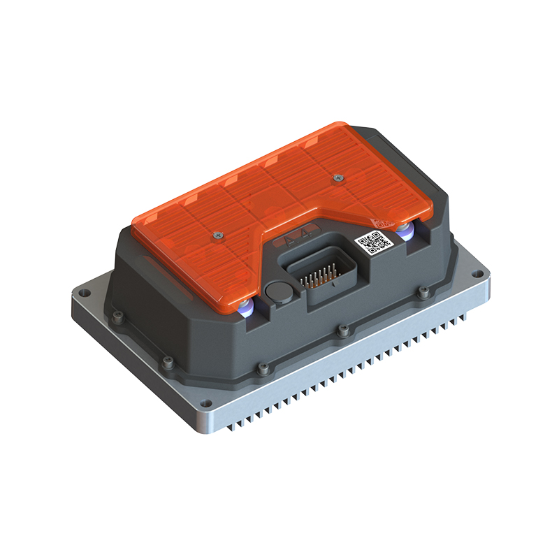
Integrated vs. External Controllers
Many modern hub motor e-bikes place the controller inside the motor housing (integrated controller) to save space and improve weather sealing. External (box-type) controllers mount separately on the frame, are user-accessible, and are the standard for DIY builds, cargo bikes, and performance e-bikes. External controllers are significantly easier to diagnose, replace, and upgrade, making them the preferred choice for anyone who wants serviceable electronics.
Key Specifications Explained
Controller specifications are frequently misquoted or misunderstood in the e-bike market. The following parameters are the ones that actually determine performance and compatibility.
| Specification | What It Defines | Typical Range | Selection Guidance |
|---|---|---|---|
| Rated voltage | Battery voltage the controller is designed for | 24V, 36V, 48V, 52V, 72V | Must match battery nominal voltage exactly |
| Phase current (A) | Max current delivered to motor windings | 15A – 80A+ | Determines torque output; must not exceed motor rating |
| Battery current (A) | Max current drawn from battery | 10A – 50A+ | Must be within battery BMS discharge rating |
| Rated power (W) | Continuous power output capacity | 250W – 3,000W+ | Match to motor rated power; legal limits vary by region |
| MOSFET count | Number of power switching transistors | 6, 9, 12, 18 FETs | More FETs = lower resistance = less heat at high current |
| Low voltage cutoff | Battery protection disconnect voltage | Set per cell count | Must match battery cell chemistry and count |
Phase Current vs. Battery Current: The Critical Distinction
Many buyers focus on the battery current rating and overlook phase current — a mistake that leads to poor performance matching. Phase current is the current flowing through the motor windings and directly determines torque. Battery current is the current drawn from the battery and determines power consumption. Due to the step-up nature of the controller's switching, phase current is always higher than battery current at low motor speeds. A controller rated for 25A battery current may deliver 40–60A phase current at low throttle settings — producing high startup torque. This relationship is why a high phase-current controller produces strong hill-climbing performance even when the battery current rating appears modest.
Understanding MOSFET Count and Thermal Performance
The MOSFETs are the most thermally stressed components in any e-bike controller. Each MOSFET has an on-resistance (RDS-on) — typically 1–5 milliohms for modern power devices — and the power dissipated as heat equals I² × RDS-on per device. Doubling the number of MOSFETs (from 6 to 12 FETs) halves the RDS-on per device of the parallel combination, reducing heat generation by roughly half. A 12-FET or 18-FET controller running a given current level runs significantly cooler than a 6-FET design, delivering longer component life and sustained power output without thermal throttling.
Compatibility: Matching Controller to Motor, Battery, and Sensors
Controller compatibility is more complex than matching voltage and power ratings. Multiple subsystems must be verified before installation to avoid damage or non-function.
Motor Phase and Hall Sensor Wiring
BLDC hub motors connect to the controller via three thick phase wires (typically color-coded yellow, green, blue) and five thin Hall sensor wires (typically red/black for power and three signal wires). The phase wire connection sequence determines the direction of motor rotation — swapping any two phase wires reverses the motor. The Hall sensor signal sequence must be matched correctly to the phase sequence; a mismatch results in the motor drawing excessive current without producing useful rotation and can rapidly damage the controller MOSFETs. Most replacement controllers require a brief phase/Hall detection procedure (supported by programmable controllers like the KT series and Lishui units) that automatically identifies the correct commutation sequence.
Battery Voltage and BMS Compatibility
The controller's rated voltage must match the battery's nominal voltage. A 48V controller will have its MOSFET voltage ratings, LVC threshold, and overvoltage protection set for a 48V lithium pack (fully charged at 54.6V for a 13S lithium-ion pack). Using a 52V battery (fully charged at 58.8V) on a controller rated for 48V maximum risks exceeding the MOSFET voltage rating during regenerative events or cold-start conditions. The battery BMS discharge current rating must also exceed the controller's maximum battery current draw — a 25A controller on a battery with a 20A BMS will cause the BMS to cut out under hard acceleration.
Throttle and PAS Sensor Compatibility
Throttles are either hall-effect (outputting 0.8–4.2V signal) or potentiometer-based. Most controllers accept hall-effect throttle signals. Pedal assist sensors (PAS) are either cadence sensors (generating a simple on/off pulse as the rider pedals) or torque sensors (generating an analog signal proportional to pedal force). Torque sensor PAS systems require specific controller firmware support and are not interchangeable with cadence-only controllers without a firmware update. Always verify the controller's PAS input type matches the installed sensor.
Display and Communication Protocol
Most aftermarket controllers communicate with the display over a simple UART serial protocol — but the specific protocol (KT-LCD, SW102, 860C, VLCD5, etc.) varies between manufacturers. Using an incompatible display results in no communication, blank screens, or erratic data. Before purchasing a replacement controller, confirm the display connector pinout and protocol. The two most common protocols in the aftermarket are the KT/Kunteng protocol and the BAFANG protocol, which are not cross-compatible.
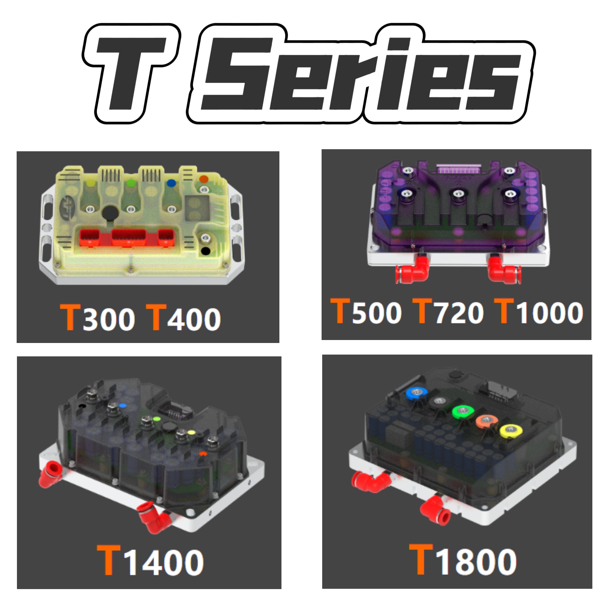
Popular E-Bike Controller Platforms and Their Characteristics
The aftermarket and OEM e-bike controller market is dominated by a small number of Chinese manufacturers whose products appear under many brand names. Understanding the underlying platforms helps evaluate quality and feature sets accurately.
| Platform | Control Type | Programmable | Voltage Range | Best For |
|---|---|---|---|---|
| KT (Kunteng) | Sine wave (most models) | Yes (via LCD display) | 24V–72V | OEM replacement, DIY builds, e-bike upgrades |
| Lishui (LSW) | Sine wave / FOC | Yes (via PC tool) | 36V–72V | Quality OEM builds, smooth-ride priority |
| Bafang (OEM) | Sine wave | Yes (via Bafang USB tool) | 36V–48V | Bafang hub motor and BBS mid-drive systems |
| Votol (EM series) | FOC sine wave | Yes (via Bluetooth app) | 48V–96V | High-power performance builds, e-motorcycles |
| Sabvoton (SVMC) | FOC sine wave | Yes (via PC software) | 48V–84V | Performance builds, BLDC and PMSM motors |
KT controllers are the most widely used in the global e-bike market due to their balance of quality, availability, and user-programmable parameters. A KT 48V 25A sine wave controller with a compatible LCD display is the most common OEM replacement solution for standard hub motor city and commuter e-bikes, covering the vast majority of 250W–750W builds.
Programmable Controller Settings and What They Control
Most quality aftermarket controllers allow user configuration of key parameters through the display unit or a PC programming tool. Understanding these settings enables meaningful customization without risking component damage.
Speed Limit and Assist Levels
The wheel circumference, wheel size, and speed limit parameters are entered to calibrate the speedometer and set the speed at which the motor cuts out. In regions where e-bikes must comply with a 25 km/h (EU) or 32 km/h (US Class 1/2) speed limit, this setting is the primary legal compliance control. PAS assist levels define how aggressively the motor responds to pedaling input at each level — from gentle supplemental assist at Level 1 to near-full throttle power at Level 5.
Current Limits and Battery Protection
The maximum battery current and phase current parameters directly control the bike's power output and acceleration character. Reducing phase current from the default (e.g., from 45A to 30A) produces a gentler, more energy-efficient ride. The low voltage cutoff must be set to match the battery's cell count and chemistry — a 48V 13S lithium-ion pack requires an LVC of approximately 42–43V (3.2–3.3V per cell) to protect cells without prematurely cutting power.
Startup Mode and Throttle Behavior
Controllers typically offer two throttle startup modes: instant response (throttle immediately produces power from standstill) and soft-start (power ramps up over 0.5–2 seconds from zero). Soft-start significantly improves ride feel and reduces mechanical shock on the drivetrain. Some controllers allow the throttle to be disabled entirely, requiring PAS as the only power input — the required configuration for legal compliance in many European jurisdictions.
Diagnosing and Replacing a Faulty E-Bike Controller
Controller failure is one of the more common electrical faults in e-bikes after battery issues. Distinguishing a controller problem from a motor, sensor, or wiring fault saves time and prevents unnecessary part replacement.
Common Controller Failure Symptoms
- Motor does not run despite power on and throttle input: Check display shows power on; verify throttle signal with a multimeter (should vary 0.8–4.2V with throttle movement). If throttle is good, controller MOSFET failure is likely.
- Motor jerks violently at startup and then stops: Classic sign of Hall sensor signal mismatch or a failed Hall sensor wire. Test each Hall sensor output (should toggle between 0V and 5V as wheel rotates).
- Motor runs in one direction only or runs without throttle input: Internal MOSFET short circuit — the controller requires immediate replacement.
- Power cuts out intermittently under load: Thermal shutdown due to inadequate cooling, or battery current limit being hit. Check controller temperature under load; verify battery current delivery.
- Burning smell or visible burn marks on the controller case: MOSFET or capacitor failure from overcurrent or overvoltage event. Replace immediately; do not attempt to operate.
Step-by-Step Controller Replacement
- Photograph all existing wiring connections before disconnecting anything. Label connectors with tape if needed.
- Disconnect the battery first, then wait 60 seconds for capacitors to discharge before handling the controller.
- Note the color coding of phase wires and Hall sensor wires at the motor connector.
- Remove the old controller and connect the new unit, matching wire colors exactly as documented.
- Before full power-on, briefly energize the Hall sensor supply only (5V from controller) and verify each Hall sensor toggles correctly as the wheel is manually rotated.
- Power on fully and test throttle at low speed in a safe area. If motor rotates in the wrong direction, swap any two of the three phase wires.
- If the motor jerks or stutters, run the controller's auto-detection routine (if supported) or manually swap Hall signal wires to find the correct commutation sequence.
- Program the controller parameters (wheel size, voltage, current limits, assist levels, speed limit) via the display before first normal use.
Upgrading Your Controller for More Performance
Upgrading the controller is one of the most cost-effective ways to improve an e-bike's power output and responsiveness, provided the motor, battery, and wiring can support the increased demands.
For a standard 48V 500W hub motor build running a 15A controller, upgrading to a 48V 25–30A sine wave controller can increase peak power output from approximately 720W to over 1,400W — roughly doubling hill-climbing ability and acceleration. However, this only works safely if:
- The motor's phase wires are heavy enough gauge to carry the increased current without overheating — minimum 14 AWG for 25A continuous, ideally 12 AWG.
- The battery BMS is rated to supply the higher discharge current continuously — check the BMS specification, not just the battery capacity rating.
- The motor's stator windings are rated for the increased phase current — most 500W–750W hub motors can safely handle up to 25–30A phase current for short periods, but sustained high current causes premature demagnetization of the rotor magnets.
- The increased power remains compliant with local regulations — in most of the EU, e-bikes are legally limited to 250W continuous assist, and exceeding this removes the bike from the legal e-bike category regardless of the hardware used.
NEXT:Electric Bicycle Mid Drive Motors: Performance & Efficiency Guide
Interested in cooperation or have questions?
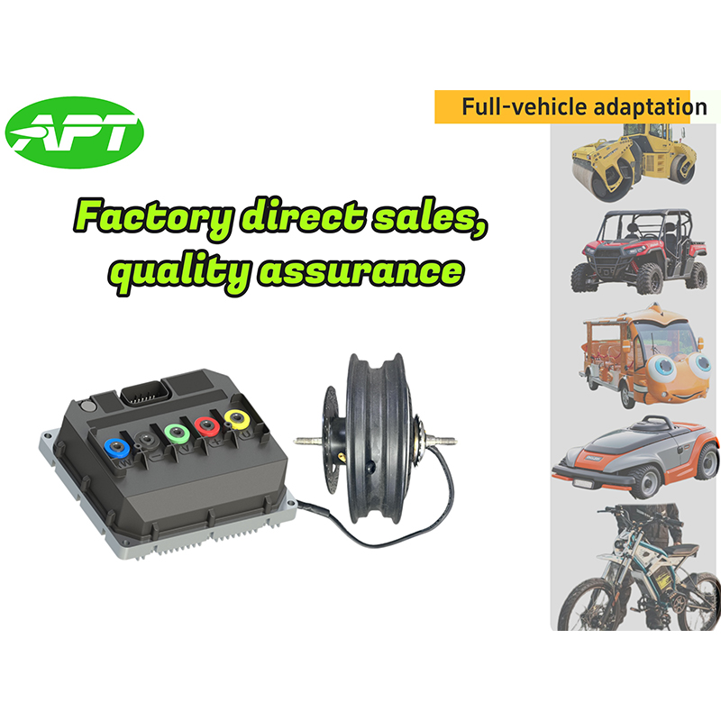

As Custom Permanent Magnet Synchronous Motor Controllers Manufacturers and Permanent Magnet Motor Controllers Suppliers in China, Focusing on the drive control of permanent magnet synchronous motors, we provide a safe and sufficient power source for the electrification of travel vehicles.
- [email protected]
- +86-170 9191 9800
- Room 123A, No. 1000 Ziyue Road, Minhang District, Shanghai, China
Copyright © Shanghai APT Power Technology Co., Ltd.All rights reserved
