 English
 Español
 عربى
عربىBrushless DC Motor Controllers: How They Work & Selection
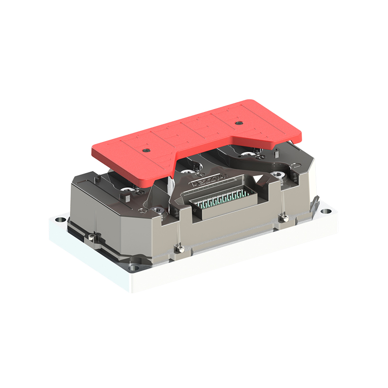
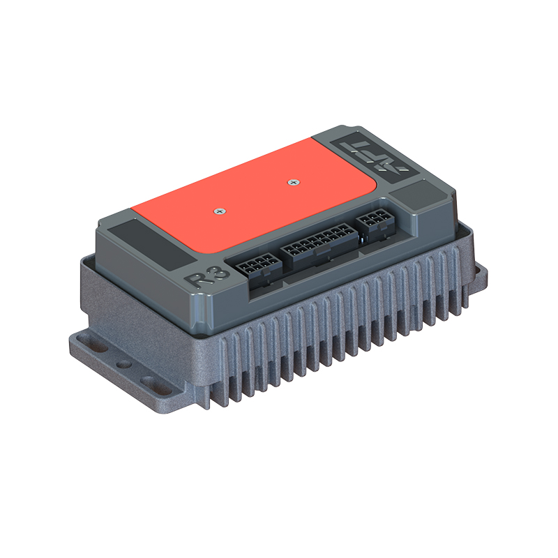
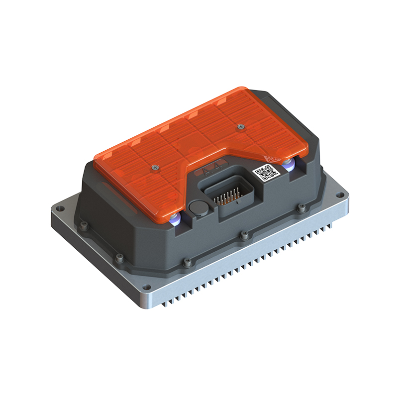
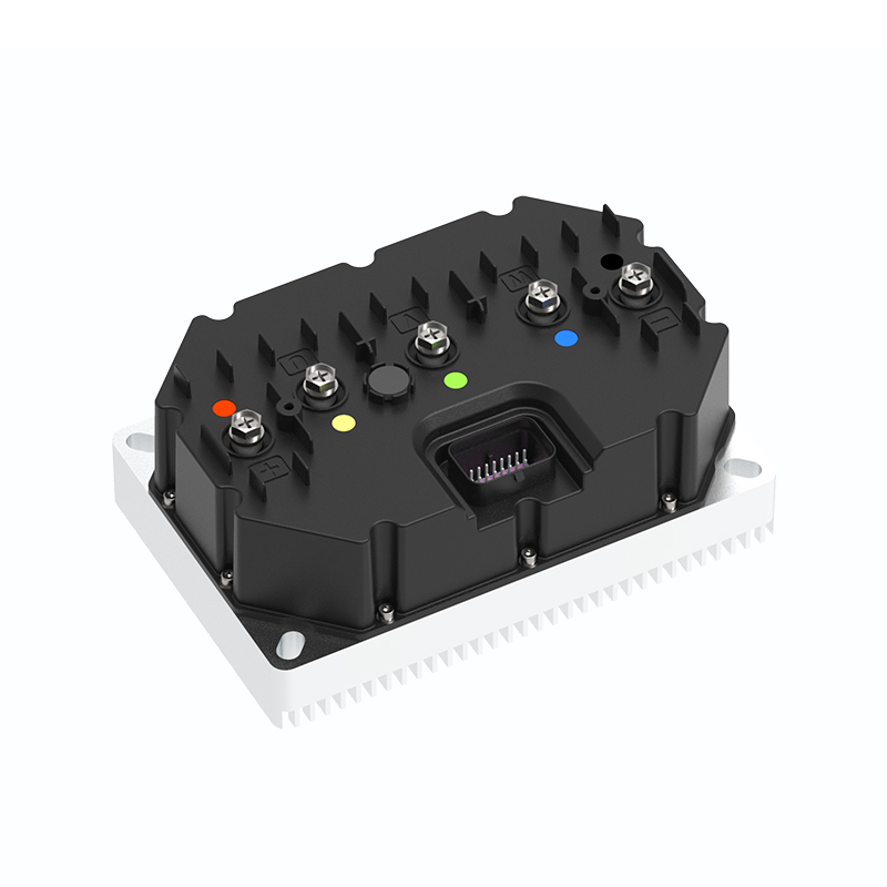
A brushless DC (BLDC) motor controller is the electronic drive that sequences power to the motor's stator windings in the correct order to produce continuous rotation, replacing the mechanical commutation that brushes perform in traditional DC motors. Without a controller, a BLDC motor cannot run — the controller is not optional hardware but an integral part of every BLDC motor system, and choosing the wrong one for your voltage, current, control method, or application load will limit performance, cause instability, or destroy the motor.
This guide covers how BLDC controllers work, the key architectural differences between controller types, the specifications that matter most for selection, and what to evaluate across different application domains from robotics and EVs to industrial automation and consumer appliances.
Content
- 1 How BLDC Motor Controllers Work
- 2 Trapezoidal vs. Sinusoidal vs. FOC Control: What Each Method Delivers
- 3 Key Specifications to Evaluate When Selecting a BLDC Controller
- 4 Controller Categories by Application Domain
- 5 Thermal Management and Power Dissipation
- 6 Protection Features That Prevent Controller and Motor Damage
- 7 Regenerative Braking and Energy Recovery
- 8 Notable Commercial BLDC Controller Platforms
- 9 Motor-Controller Matching: The Parameters That Must Align
How BLDC Motor Controllers Work
A BLDC motor has three stator windings (phases) arranged around the rotor. To produce rotation, current must be applied to these windings in a sequence that creates a rotating magnetic field the permanent magnet rotor follows. The controller's job is to determine the rotor's current position and switch current to the correct winding pair at the correct moment — a process called electronic commutation.
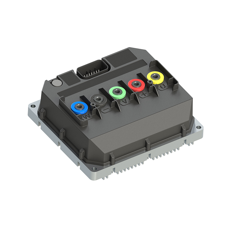
The power stage consists of a three-phase bridge of six switching transistors — typically MOSFETs or IGBTs — arranged in three high-side/low-side pairs, one for each motor phase. By turning specific transistors on and off, the controller routes DC bus voltage to any combination of phase windings. The control logic determines which transistors fire and when, based on rotor position feedback.
The switching pattern is modulated using PWM (pulse-width modulation) — the duty cycle of the PWM signal controls the average voltage applied to the windings and therefore the motor speed and torque. A controller running at a PWM frequency of 20–100 kHz applies voltage in rapid pulses that the motor's inductance smooths into effective continuous current, far more efficiently than a linear regulator could achieve.
Hall Sensor Commutation vs. Sensorless Commutation
Rotor position can be determined two ways, and the method fundamentally affects controller design and application suitability:
- Hall sensor commutation: Three Hall-effect sensors embedded in the motor stator detect the rotor magnet position and send digital signals directly to the controller. This provides reliable position data at all speeds including standstill and during starting under load. Hall sensors add wiring complexity (typically a 5-wire sensor harness) and a potential failure point, but deliver robust, predictable commutation. Used in applications requiring controlled starting torque: fans, pumps, EV motors, servo drives.
- Sensorless commutation (back-EMF detection): As the motor spins, each non-energized phase generates a back-EMF voltage proportional to speed. The controller monitors this voltage to determine rotor position. Eliminates sensor wiring entirely but cannot detect position at zero speed — requiring an open-loop starting sequence before transitioning to sensorless operation. Widely used in drone propulsion (ESCs), computer fans, and appliance motors where starting under no-load or light load is the norm.
Some controllers support both modes — using Hall sensors for startup and transitioning to sensorless operation at running speed for reduced wiring complexity in long-term service.
Trapezoidal vs. Sinusoidal vs. FOC Control: What Each Method Delivers
The commutation strategy — the mathematical method the controller uses to calculate when and how much current to apply to each phase — determines the motor's torque smoothness, efficiency, noise level, and dynamic response. Three strategies dominate commercial BLDC controllers.
Trapezoidal (Six-Step) Commutation
The simplest strategy: the three phases are energized in six discrete steps per electrical revolution. At any moment, two phases carry current and the third is open. Switching occurs at 60° electrical intervals based on Hall sensor inputs or back-EMF zero crossings.
Trapezoidal control is computationally lightweight and easy to implement, making it the dominant method in cost-sensitive applications. Its limitation is torque ripple — the discrete switching produces torque variation of 10–15% per electrical cycle, which translates to vibration and acoustic noise. Acceptable for fans, pumps, and power tools; problematic for precision positioning or smooth-running servo applications.
Sinusoidal Commutation
Instead of discrete steps, sinusoidal commutation applies smoothly varying sinusoidal current to all three phases simultaneously, creating a smoothly rotating magnetic field. Torque ripple drops to 2–5% compared to trapezoidal control, motor noise is significantly reduced, and operation is smoother particularly at low speeds. Requires more processing power than trapezoidal commutation and a higher-resolution position sensor (encoder or resolver) for best results, though it can also be implemented with Hall sensors using interpolation.
Field-Oriented Control (FOC / Vector Control)
FOC is the most sophisticated control method, mathematically transforming the three-phase motor currents into two independent DC quantities — the flux-producing component (Id) and the torque-producing component (Iq). By controlling these independently, the controller can maintain optimal motor efficiency at any speed and load, achieve near-zero torque ripple, and deliver very fast dynamic torque response.
FOC typically improves system efficiency by 5–15% over trapezoidal commutation in variable-load applications because it minimizes reactive current that produces heat without producing torque. It requires a DSP or microcontroller capable of executing the Clarke and Park transforms in real time — typically a 32-bit ARM Cortex-M or dedicated motor control DSP. FOC is the standard method in EV traction drives, industrial servo drives, and premium appliance motors.
| Control Method | Torque Ripple | Efficiency | Noise Level | Processing Requirement | Best Applications |
|---|---|---|---|---|---|
| Trapezoidal (6-step) | 10–15% | Good | Higher | 8-bit MCU sufficient | Fans, pumps, power tools, ESCs |
| Sinusoidal | 2–5% | Very good | Low | 32-bit MCU preferred | Appliances, HVAC, smooth drives |
| FOC (Vector Control) | <1% | Excellent | Very low | DSP or 32-bit MCU required | EVs, servo drives, robotics, CNC |
Key Specifications to Evaluate When Selecting a BLDC Controller
Controller datasheets contain many parameters. These are the specifications that directly determine whether a controller is appropriate for a given motor and application.
Supply Voltage Range
The controller's rated input voltage range must include your power supply voltage with adequate headroom. Operating a controller at its absolute maximum voltage rating leaves no margin for voltage transients — regenerative braking, load dump from inductive switching, or supply instability can spike the bus voltage 20–50% above nominal for microseconds. For a 48V nominal system, a controller with an 80V or 100V absolute maximum rating provides realistic protection margin.
The most common voltage ranges encountered in commercial BLDC controllers span from small robotics and drone systems at 7.4–22.2V (2–6S LiPo) up through industrial drives at 24V, 48V, and 96V DC bus systems. High-power EV and industrial applications use 200–800V DC bus controllers requiring IGBTs rather than MOSFETs as switching elements.
Continuous and Peak Current Ratings
Controllers specify two current ratings that are often confused. Continuous current is the sustained phase current the controller can handle indefinitely at a specified case or ambient temperature. Peak current is the maximum instantaneous current the controller can supply for a short duration (typically 1–30 seconds) before thermal protection activates.
The motor's rated phase current must not exceed the controller's continuous current rating under normal operating conditions. If the application involves frequent acceleration peaks or starting under load, the peak current rating must also accommodate the required peak torque current — typically 2–4× the continuous rating for brief intervals. Selecting a controller with a continuous rating equal to the motor's peak current is a common oversizing approach for high-cycle or high-inertia load applications.
PWM Frequency
PWM frequency determines current ripple magnitude, switching losses, and acoustic noise. Higher PWM frequency reduces current ripple (improving torque smoothness) and pushes switching noise above human hearing at 20 kHz+, but increases switching losses in the power transistors.
- 8–16 kHz: Common in cost-optimized controllers; may produce audible 8 kHz whine
- 20–40 kHz: Silent operation in most conditions; standard for quality consumer and industrial BLDC controllers
- 40–100 kHz: Used in high-performance servo controllers; requires fast-switching MOSFETs (low gate charge) and increases heat generation in the power stage
Position Sensor Interface
The controller must support the position sensor type used in or with the motor:
- Hall sensor (digital, 3-wire): Lowest resolution (6 positions per electrical revolution); adequate for speed control, not sufficient for precision position servo
- Incremental encoder (quadrature A/B + index): Resolutions of 100–10,000 PPR common; required for moderate precision positioning
- Absolute encoder (SSI, BiSS-C, EnDat): Single-turn or multi-turn absolute position data; required for servo axes that must know position at power-on without homing
- Resolver: Analog position feedback preferred in high-temperature or high-vibration environments (automotive, aerospace); requires dedicated resolver-to-digital converter (RDC) in the controller
- Sensorless: Back-EMF or flux observer-based; no sensor wiring required
Communication and Command Interface
How speed, torque, and position commands are sent to the controller determines its integration into a larger system. Common interfaces include:
- Analog (0–5V or 0–10V): Simple, universal, inherently noisy; used in basic speed control
- PWM input: Standard for RC/drone ESCs and many consumer applications
- RS-232/RS-485/UART: Serial communication for configuration and control in embedded systems
- CAN bus: Standard in automotive and industrial multi-node systems; robust, noise-immune, supports multiple controllers on one bus
- CANopen / EtherCAT / Profibus: Industrial fieldbus protocols for motion control systems integrating with PLCs and motion controllers
- USB / SPI / I²C: Common in development and evaluation boards, hobbyist, and embedded microcontroller integration
Controller Categories by Application Domain
BLDC controllers are not a single product category — they span from gram-scale ESCs to kilowatt industrial drives. Understanding the category that fits your application prevents both over-engineering and under-specifying.
| Category | Voltage Range | Current Range | Control Method | Typical Applications |
|---|---|---|---|---|
| Drone/RC ESC | 7–52V (2–12S) | 10–100A | Sensorless trapezoidal or sinusoidal | Multirotor drones, fixed-wing, RC vehicles |
| Robotics / AGV | 12–72V | 5–100A | FOC, encoder/Hall feedback | Robot joints, wheels, mobile platforms |
| Industrial Servo | 48–800V DC | 1–500A | FOC with absolute encoder | CNC axes, pick-and-place, conveyor servo |
| EV Traction | 48–800V | 100–1,000A | FOC with resolver or encoder | E-bikes, scooters, EVs, golf carts |
| HVAC / Appliance | 12–340V DC (rectified AC) | 0.5–30A | Sensorless or sinusoidal | Compressors, fans, pumps, washing machines |
| Development / Eval | 12–60V | 5–50A | Configurable (FOC, trap, sine) | Prototyping, research, custom motor tuning |
Thermal Management and Power Dissipation
Controller power dissipation comes from two sources: conduction losses in the MOSFETs and switching losses during each transistor on/off transition. At 95% system efficiency — typical for a well-designed BLDC controller at rated load — a 1,000W drive dissipates approximately 50W as heat in the controller electronics.
MOSFET junction temperature must remain below the rated limit — typically 150–175°C junction temperature for silicon MOSFETs — with a thermal margin for transients. The thermal path from MOSFET junction to ambient determines how much power can be continuously dissipated. This path has three resistances in series: junction-to-case (R_th,jc — a property of the MOSFET package), case-to-heatsink (determined by thermal interface material and mounting), and heatsink-to-ambient (determined by heatsink area and airflow).
Practical thermal management approaches in commercial BLDC controllers:
- Aluminum extrusion heatsink with natural convection: Adequate for controllers up to 500W in open-air mounting; no moving parts, no maintenance
- Forced-air cooling (fan over heatsink): Extends the continuous power rating of a given heatsink by 2–4×; fan adds noise and is a wear/failure item
- Cold plate (liquid cooling): Standard for EV traction controllers and high-power industrial drives above 5–10 kW; very high power density, requires coolant loop infrastructure
- PCB copper pour heatspreading: Used in compact low-power controllers (under 200W); MOSFETs mounted directly on heavy copper PCB traces that conduct heat to the board edges
Thermal shutdown and derating circuits are essential protection features — a controller without over-temperature protection will operate the MOSFETs past their safe operating area if ambient temperature rises or airflow is restricted, resulting in MOSFET failure that is often catastrophic and permanent. Always verify that the selected controller includes both thermal monitoring and automatic current derating or shutdown before thermal limits are reached.
Protection Features That Prevent Controller and Motor Damage
A BLDC controller operating in a real application is exposed to fault conditions that can destroy it or the motor within milliseconds if unprotected. The following protections are not optional — their presence or absence distinguishes industrial-grade controllers from budget designs.
- Over-current protection (OCP): Detects phase current exceeding the rated limit and disables the output within microseconds. Implemented in hardware (comparator-based) for fastest response — software OCP loops are too slow to prevent MOSFET destruction in a hard short circuit.
- Over-voltage protection (OVP): Detects DC bus voltage exceeding safe limits — commonly caused by regenerative braking returning energy to the bus when no dissipation path exists. OVP either activates a braking resistor circuit or faults the controller output. Operating a 48V controller at 60V+ without OVP will destroy the MOSFETs.
- Under-voltage protection (UVP): Prevents operation when supply voltage drops below the minimum required for reliable gate drive and control logic — important for battery-powered systems where deeply discharged batteries can cause unpredictable controller behavior.
- Over-temperature protection (OTP): Thermal sensor (NTC or on-chip temperature sensor) monitors MOSFET or PCB temperature and reduces current limit or shuts down before thermal damage occurs.
- Shoot-through prevention (dead-time insertion): In a half-bridge, turning on both the high-side and low-side transistors simultaneously creates a direct short across the supply — called shoot-through. Gate driver ICs insert a programmable dead time (typically 100–500 ns) between turning one transistor off and the complementary transistor on, preventing this condition.
- Motor stall detection: Detects zero or near-zero speed under continued current application, indicating a mechanically stalled motor. Without stall detection, a stalled BLDC motor draws locked-rotor current continuously — typically 5–10× normal running current — until the motor windings overheat and fail.
Regenerative Braking and Energy Recovery
When a BLDC motor decelerates under active braking, it acts as a generator, returning energy back toward the DC bus. Whether this energy is recovered, dissipated, or simply becomes a problem depends on the controller's design and the application's energy storage capability.
Three approaches to handling regenerative energy:
- Regenerative recovery to battery or capacitor: The controller allows current to flow back into the energy source during braking. Requires a battery chemistry that accepts regenerative charging (most Li-ion and NiMH cells do) and a controller designed to manage bidirectional current flow. Used in EVs, e-bikes, and robotics — in EV systems, regenerative braking can recover 10–25% of the energy that would otherwise be lost as heat.
- Regenerative braking resistor (dynamic braking): The controller diverts regenerative current through a resistor (braking chopper circuit) when bus voltage exceeds a threshold. Energy is dissipated as heat rather than recovered. Used when the supply cannot accept reverse current — non-regenerative industrial DC bus supplies or capacitor banks without sufficient energy storage.
- Coasting / passive braking: The controller disables all output during deceleration, allowing the motor to coast down. No active braking, no energy recovery. Simplest approach; acceptable only where deceleration time and load momentum permit it.
Notable Commercial BLDC Controller Platforms
The commercial BLDC controller market spans from open-source development platforms to closed industrial drives. Several platforms have achieved broad adoption in their respective domains and are worth understanding as reference points.
ODrive and VESC (Open-Source Robotics / Research)
The ODrive (versions 3.6 and S1) and VESC (Vedder Electronic Speed Controller) are open-source FOC controllers widely used in robotics, electric skateboards, and research applications. Both support Hall sensor and encoder feedback, USB/CAN communication, and configurable FOC parameters through PC software. ODrive S1 handles up to 60V and 60A continuous; VESC-based controllers span a wide range depending on the hardware implementation. Their open-source nature allows deep customization but requires more tuning effort than turnkey industrial drives.
Texas Instruments InstaSPIN and MotorWare
TI's InstaSPIN-FOC is a sensorless FOC algorithm implemented in ROM on their C2000 series DSPs, enabling FOC without an encoder. The accompanying MotorWare and Code Composer Studio tools provide an integrated development environment for custom BLDC controller firmware. This platform is widely used in industrial drives, appliances, and power tools where custom controller development on TI silicon is the design approach.
Trinamic (Analog Devices) Integrated Driver ICs
Trinamic's TMC6100, TMC6200, and related gate driver ICs integrate MOSFET gate drivers, current sensing, and protection circuits in a compact package designed to interface with an external MCU. These are the building blocks for custom compact BLDC controllers in space-constrained applications — robotics joints, gimbal motors, and embedded drives where board size matters.
Industrial Servo Drives (Kollmorgen, Beckhoff, Siemens)
For industrial CNC, automation, and high-performance motion control, complete servo drive systems from manufacturers like Kollmorgen (AKD series), Beckhoff (AX series), and Siemens (SINAMICS S series) provide FOC control with EtherCAT or Profinet communication, absolute encoder support, and all safety functions required for CE-marked machine integration. These are not open platforms but offer the reliability, certifications, and vendor support required for production machinery with defined SIL or PLe safety requirements.
Motor-Controller Matching: The Parameters That Must Align
A BLDC motor and controller must be matched as a system. Mismatches between their parameters are the most common cause of poor performance, instability, or hardware failure in BLDC drive systems.
- Motor KV rating vs. operating voltage: The KV rating (RPM per volt) of the motor must produce the required speed at the available bus voltage. A 500 KV motor at 48V reaches a theoretical no-load speed of 24,000 RPM — confirm the controller, motor, and mechanical load are all rated for this speed range.
- Motor phase resistance and controller current loop bandwidth: The controller's current control loop bandwidth must be set appropriately for the motor's electrical time constant (L/R). A low-inductance motor requires a faster current loop; using default current loop gains tuned for a high-inductance motor on a low-inductance motor produces current ripple and instability.
- Motor pole count and maximum electrical frequency: The electrical frequency the controller must commutate equals (RPM × pole pairs / 60). A 12-pole motor (6 pole pairs) running at 6,000 RPM requires the controller to commutate at 600 Hz electrical frequency — confirm the controller's maximum commutation frequency supports this. High-pole-count outrunner motors in robotics can require commutation rates that exceed the capability of low-cost controllers.
- Motor phase current at rated torque vs. controller continuous current: Calculate motor phase current from the torque requirement: I = T / (KT × √2), where KT is the motor torque constant. This value must be within the controller's continuous current rating at the operating duty cycle.
- Sensor interface compatibility: Verify that the Hall sensor supply voltage matches the controller's output (5V vs. 3.3V logic), and that encoder signal levels and protocols are compatible before assuming any motor-controller combination will work at the electrical interface level.
The safest approach when building a custom BLDC drive system is to use a motor and controller from the same manufacturer or from a supplier that provides a validated compatibility matrix. When integrating components from different sources, perform a bench test at low voltage and no-load before committing to the full operating voltage and mechanical load — MOSFET failures from mismatched control parameters are rarely recoverable, and the diagnostic evidence is typically destroyed in the failure event.
NEXT:Electric Bike Controller: How It Works, Types & Selection
Interested in cooperation or have questions?
As Custom Permanent Magnet Synchronous Motor Controllers Manufacturers and Permanent Magnet Motor Controllers Suppliers in China, Focusing on the drive control of permanent magnet synchronous motors, we provide a safe and sufficient power source for the electrification of travel vehicles.
- [email protected]
- +86-170 9191 9800
- Room 123A, No. 1000 Ziyue Road, Minhang District, Shanghai, China
Copyright © Shanghai APT Power Technology Co., Ltd.All rights reserved
