 English
 Español
 عربى
عربى
How Do Electronic Speed Controllers Work? Inside the ESC's Signal Chain
A 48 V battery pack delivers one fixed DC voltage. A motor on an electric scooter still has to hold roughly 3,200 rpm on a flat road, drop to about 280 rpm on a 12 percent grade, and reverse on demand. Something between the battery and the windings has to decide how much current flows, in which direction, and for how long.
That device is the electronic speed controller. It works by converting the battery's fixed DC into a three-phase output and switching that output thousands of times per second. The average voltage the motor sees rises and falls with the duty cycle, and the motor's own inductance turns those fast pulses into smooth current. Torque follows current, and speed settles where motor torque meets load torque. Everything else inside an ESC exists to make that happen safely and repeatably.
Content
- 1 How DC Becomes Three-Phase Rotation
- 2 The Signal Chain From Throttle Input to Gate Drive
- 3 Duty Cycle, PWM, and the Numbers That Matter
- 4 Matching a Controller to a Motor Without Guesswork
- 5 Firmware, Protocols, and Tuning
- 6 Thermal Reality and Reliability Limits
- 7 What to Check Before You Buy
- 8 The Short Version
How DC Becomes Three-Phase Rotation
A brushless motor will not run on DC applied to two terminals. Its stator carries three phase windings and its rotor carries permanent magnets, so current has to move through the phases in sequence to keep the stator field pulling the rotor forward instead of holding it in place.
Commutation: staying ahead of the rotor
Commutation is the act of choosing which phase pair is energized. In six-step commutation, each electrical revolution is split into six states, and the controller turns on one high-side and one low-side switch per state, producing a field that steps forward every 60 electrical degrees. If commutation lags behind the rotor, torque collapses and current climbs. If it leads too far, the extra current becomes heat instead of torque.
Sensored and sensorless position feedback
Three Hall sensors report absolute rotor position, which matters for a robot chassis that has to start from a standstill under full load. Sensorless schemes instead read the back-EMF induced in the unenergized phase and estimate position from its zero crossing. That removes three wires and a connector from the harness, but the estimate becomes unreliable below roughly 5 to 10 percent of rated speed. Field-oriented control goes further, transforming the measured phase currents into a rotating reference frame and regulating the torque-producing component directly.
The Signal Chain From Throttle Input to Gate Drive
Between the throttle input and the motor terminals sit four functional blocks. Each has its own failure mode and its own limit on system performance.
Microcontroller and control loop
The microcontroller samples phase current, bus voltage, throttle position, and rotor position, often 8,000 to 20,000 times per second in a field-oriented implementation. It runs the fast current loop first, wraps a slower speed or torque loop around it, and converts the result into three duty cycle values. Throttle mapping, current limits, regenerative braking strength, and fault thresholds all live in this layer.
Gate driver and MOSFET bridge
The gate driver translates low-voltage logic into the 10 to 15 V swing a power MOSFET needs, and it prevents both switches in one leg from conducting at the same time. Dead time, the deliberate blanking interval between the high-side turning off and the low-side turning on, is typically 0.3 to 1 microsecond. Too short and shoot-through current destroys the bridge; too long and low-speed torque and efficiency both suffer.
Six MOSFETs form the three-phase bridge, where conduction loss scales with on-resistance and current squared, while switching loss scales with switching frequency, bus voltage, and gate charge. Paralleling devices lowers on-resistance, but only when gate loops are matched. Otherwise one device carries more current than its neighbours and fails first.
Current sensing and protection
Shunt resistors or Hall-effect sensors measure phase current so the control loop has something real to regulate, and the same signals feed overcurrent, overvoltage, and overtemperature protection. A well-behaved controller folds current back gradually as temperature rises instead of cutting the motor mid-manoeuvre.
Duty Cycle, PWM, and the Numbers That Matter
Speed control is duty cycle control. If the bus sits at 48 V and the duty cycle is 50 percent, the motor sees an average of 24 V. Switching frequency is chosen high enough to hold current ripple inside a practical band and low enough to keep switching loss manageable. On a 48 V drive with a few hundred microhenries of phase inductance, 16 kHz to 20 kHz usually keeps ripple near 10 to 20 percent of rated current.
| Parameter | What it influences | Practical range |
|---|---|---|
| PWM switching frequency | Current ripple, audible noise, switching loss | 16 to 20 kHz |
| Control loop rate | Torque response, stability margin | 8 to 20 kHz |
| Continuous phase current | Cruise torque, steady-state heating | 60 to 80 percent of peak rating |
| Peak current, 10 s | Acceleration and stall torque | 1.5 to 2 times continuous |
| Bus voltage headroom | Regenerative braking, load dump | 1.25 to 1.5 times nominal bus |
| Dead time | Shoot-through risk against low-speed efficiency | 0.3 to 1 microsecond |
| Gate resistance | Switching speed, ringing, EMI | 2 to 10 ohm |
Read the table as a set of trade-offs rather than a specification. Raising switching frequency shrinks ripple and quiets the drive, but it also raises switching loss and heat. Widening dead time protects the bridge, yet it distorts the output voltage at low duty cycle, which shows up as rough starting and extra low-speed heating.
Matching a Controller to a Motor Without Guesswork
The most common sizing error is choosing a controller by the motor's label power. Motors are rated by mechanical output; controllers are limited by phase current and junction temperature. A 1 kW motor can pull 40 A of phase current at 48 V during a hard start from rest, even though its cruise current is closer to 12 A. Size for the start, not the cruise, and check three numbers together:
- Continuous phase current at the expected ambient temperature, not at 25 C.
- Bus voltage range with headroom for the regenerative braking spike.
- Thermal path: heatsink area, airflow, and how long peak current can be sustained.
Published pairing tables remove most of that guesswork, because they state which controller and motor combinations have already been characterized for current, voltage, and mounting.
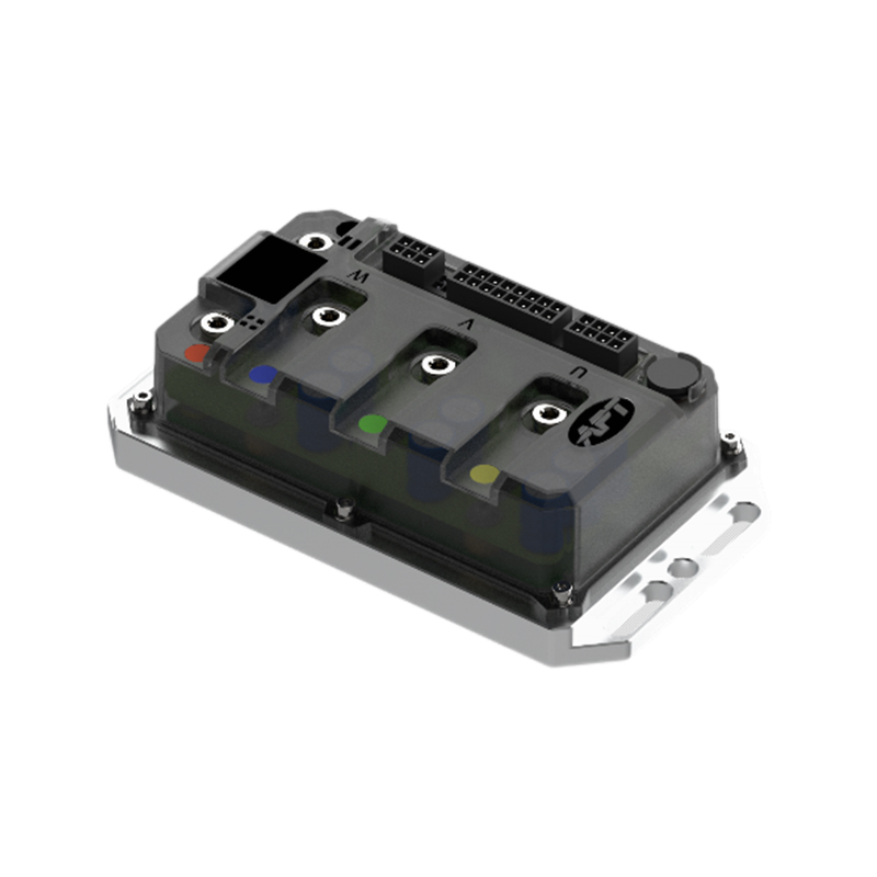 APT Controller and Motor Pairing SchemeB2B pairing advice for matching APT controllers and motors across power, torque, speed, and efficiency, with protocol considerations for electric vehicles.View Product →
Firmware, Protocols, and Tuning
Two controllers with identical power stages can behave very differently. The input protocol is the first difference: PWM and analog inputs are simple and low-latency, UART suits parameter tuning and telemetry, and CAN bus fits vehicles where the controller, battery management system, and vehicle control unit need to share state.
The second difference is firmware. Throttle curves, current ramps, regenerative braking profiles, field weakening for top speed, and fault recovery behaviour are all software decisions, and the role of software in modern motor controllers has grown to match the power stage itself. Ask for the parameter set before you commit to a platform, not after the first prototype stalls on a hill.
Thermal Reality and Reliability Limits
Datasheet current ratings usually assume a 25 C ambient and a MOSFET case held near 80 C. Inside a sealed enclosure on a summer afternoon, neither condition holds. Conduction loss rises with temperature because on-resistance increases, which raises loss again; without derating, that loop runs away. Practical derating for a passively cooled controller is often 30 to 40 percent below the headline current. Capacitors deserve equal attention, since their ripple current rating and rated life at 105 C set the real service interval, not the MOSFET part number.
For applications that cannot tolerate nuisance trips, stability across temperature and load matters more than a peak figure on a first page.
APT A8 High Stability Brushless DC Motor ControllerA characterized high-stability brushless DC motor controller with FOC, CAN, Bluetooth, and 30 kW peak for drones, robotics, and light EVs.View Product →What to Check Before You Buy
- Phase current at the worst-case condition: full-load start, maximum grade, highest ambient.
- Bus voltage window, including the regenerative spike your battery will actually see.
- Control interface: does the vehicle already speak CAN, or will PWM do the job?
- Thermal design: heatsink area, airflow path, and mounting orientation.
- Protection and reporting: overcurrent, overvoltage, overtemperature, and whether faults are logged or only signalled.
- Support: parameter documentation, firmware update path, and whether the supplier will characterize your motor with their controller.
Suppliers who publish a characterized controller range and matching guidance make that last point far easier to verify before tooling is committed.
APT R5 Fast Response Brushless DC Motor ControllerA characterized fast-response brushless DC/PMSM controller with 5 kW rated, 12 kW peak, CAN, and FOC for robotics, automation, and mini-EVs.View Product →The Short Version
- An ESC converts fixed DC into a switched three-phase output, and duty cycle sets the average voltage and therefore the speed.
- Commutation keeps the stator field ahead of the rotor; Hall sensors handle low speed, back-EMF estimation handles cruise.
- The microcontroller, gate driver, MOSFET bridge, and current sensing each impose their own limit on the system.
- Size by phase current at the worst-case condition, then derate for the ambient temperature the product will really see.
- Firmware and parameter access shape drive behaviour far more than the switch part numbers do.
NEXT:Field Weakening Explained: How Motor Controllers Push Speed Beyond Base Rating
Interested in cooperation or have questions?
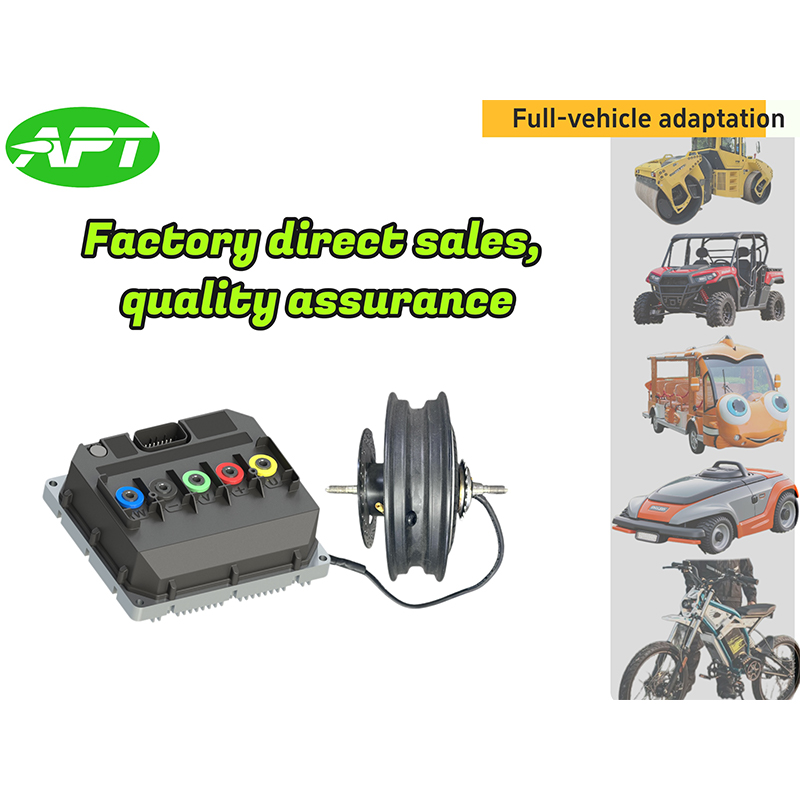
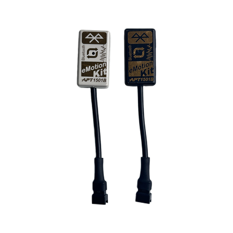
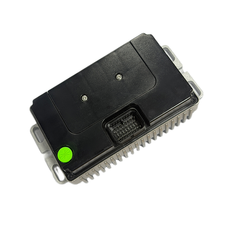
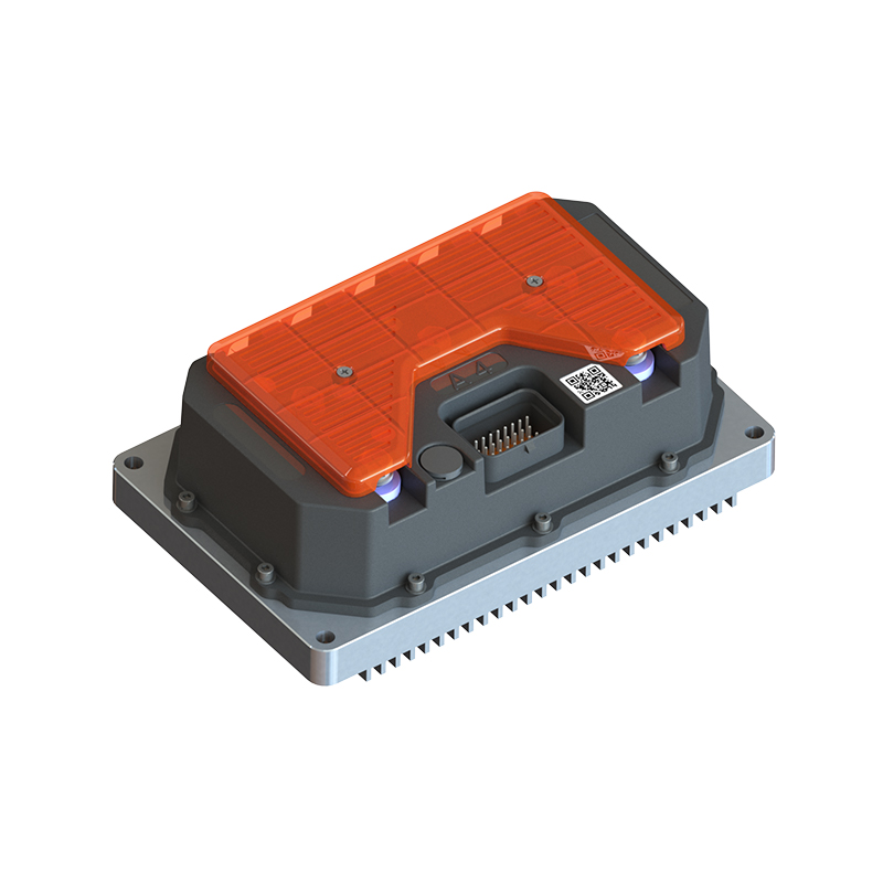
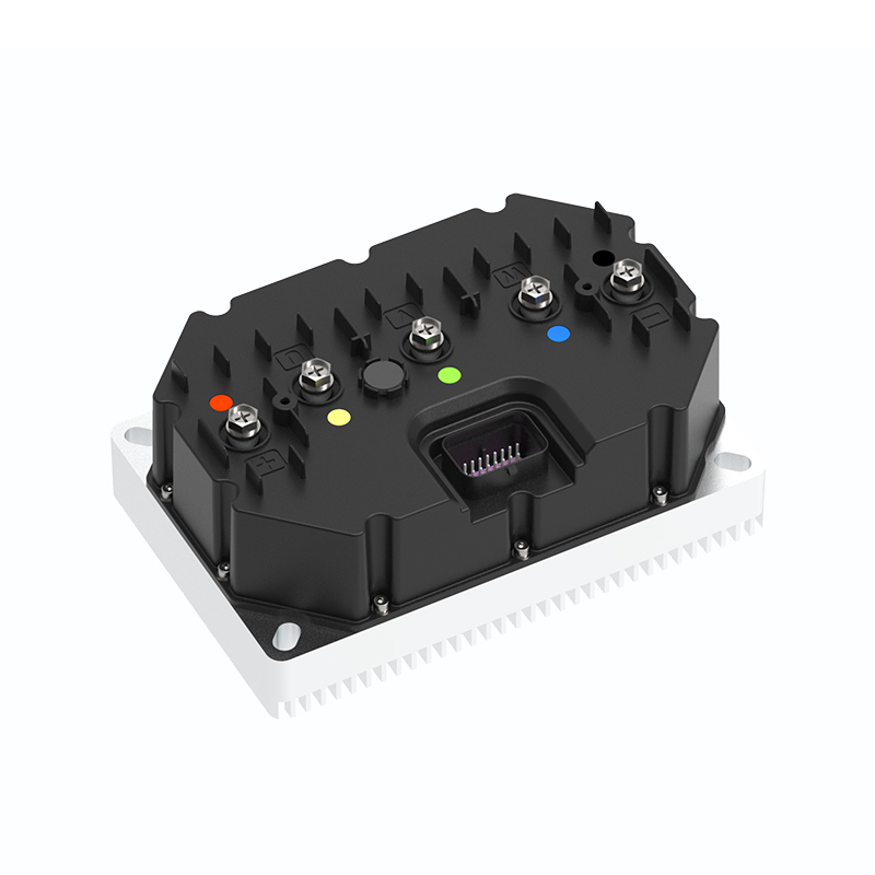

As Custom Permanent Magnet Synchronous Motor Controllers Manufacturers and Permanent Magnet Motor Controllers Suppliers in China, Focusing on the drive control of permanent magnet synchronous motors, we provide a safe and sufficient power source for the electrification of travel vehicles.
- [email protected]
- +86-170 9191 9800
- Room 123A, No. 1000 Ziyue Road, Minhang District, Shanghai, China
Copyright © Shanghai APT Power Technology Co., Ltd.All rights reserved

