 English
 Español
 عربى
عربى
Motor Encoder Selection for BLDC Drives: Resolution, Interface and Fit
Two electric motorcycle prototypes arrived at the same test bench with the same 10-inch hub motor, the same controller firmware and the same battery pack. One crept forward at walking pace with a smooth, controllable pull. The other juddered below 3 km/h and cooked a phase winding after twenty minutes of hill starts. The mechanical parts were identical; the feedback path was not. One motor carried a 1,024 PPR incremental encoder, the other a set of three Hall sensors and a firmware table that estimated rotor position between commutation steps.
The lesson is easy to state and easy to forget during procurement: on a brushless DC or permanent magnet synchronous drive, the motor encoder decides how finely and how reliably the controller can know where the rotor is. Resolution, output interface, mechanical mounting and operating environment all feed one number — the quality of position information reaching the control loop. Treat the encoder as an accessory and you pay for it in torque ripple, rejected first articles or field returns.
Content
- 1 What a motor encoder does inside a closed-loop drive
- 2 Incremental or absolute: match the encoder to start-up behaviour
- 3 Resolution, accuracy and the numbers worth comparing
- 4 Interfaces, cables and the noise that corrupts feedback
- 5 Mechanical fit and environment: where field failures begin
- 6 Applications and what each one demands
- 7 A validation checklist before you release the design
What a motor encoder does inside a closed-loop drive
An encoder converts mechanical motion into an electrical signal that the drive can count, clock or decode. In a three-phase brushless drive, the controller needs the rotor electrical angle to decide when to switch each MOSFET. Hall sensors deliver six discrete states per electrical revolution: enough for six-step commutation, too coarse for smooth low-speed torque. An encoder adds continuous position — incremental types emit A/B quadrature pulses with an optional index pulse, while absolute types report a coded position value the moment power is applied.
That difference shapes the whole machine, not just the sensor. With incremental feedback, the controller must perform a homing move after every power cycle to establish a zero reference. With absolute feedback, the machine knows where it is immediately, which matters for a robot chassis that must resume a route without a reference run, and for steering or actuator axes where unexpected movement at start-up is a safety issue. Much of the interpolation, filtering and fault detection that once lived in dedicated hardware now sits in firmware, which is why the role of software in modern motor control keeps expanding.
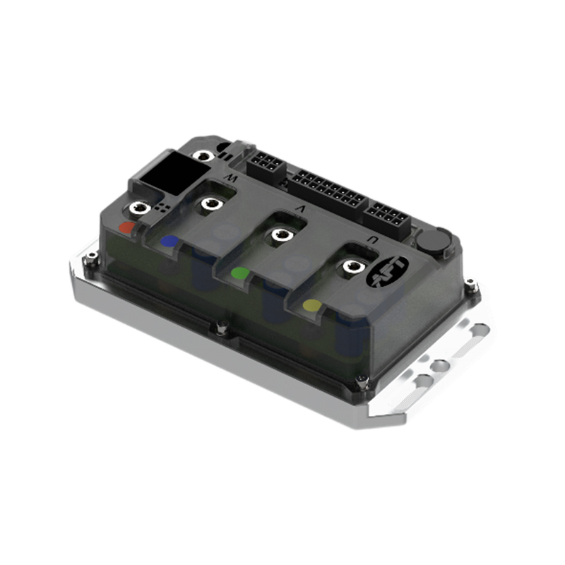 A6 2422 Ultra-Quiet Brushless DC Motor ControllerFor systems weighing incremental versus absolute feedback, this controller supports Hall or magnetic encoder input and FOC vector control.View Product →
Incremental or absolute: match the encoder to start-up behaviour
Start with one question: what happens in the first 200 milliseconds after the key is turned? If the machine can tolerate a slow reference move, an incremental encoder is cheaper and simpler to integrate. If it cannot, absolute feedback is the honest answer, and the extra cost belongs in the budget from the beginning rather than in a redesign six months later.
| Feedback type | Output signal | Typical fit | Main risk |
|---|---|---|---|
| Hall sensor set | Three digital states per electrical cycle | Commutation only, cost-driven drives | Rough low-speed torque, no fine position |
| Incremental optical | A/B quadrature, index, 5 V TTL or 24 V HTL | Precision speed and position on sealed axes | Disc contamination kills the signal outright |
| Incremental magnetic | A/B quadrature, index | Dust, moisture and vibration in e-mobility | External magnetic fields, air-gap tolerance |
| Absolute single-turn | SSI, BiSS-C, SPI or PWM | Start-up without homing, robot joints | Higher cost, protocol support in the drive |
| Absolute multi-turn | Serial with revolution counter | Actuators, steering, geared axes | Counter errors after long storage or vibration |
Resolution, accuracy and the numbers worth comparing
Incremental resolution is quoted in pulses per revolution. A 1,024 PPR encoder read in four-fold quadrature yields 4,096 counts per revolution. On a 250 mm diameter wheel with a 785 mm circumference, one count equals roughly 0.19 mm of travel — acceptable for odometry, marginal for precise positioning. A 17-bit absolute encoder delivers 131,072 counts per revolution, about 0.006 mm on the same wheel, and its resolution does not collapse when the machine moves slowly.
Resolution is not accuracy. Interpolation error inside the encoder, shaft eccentricity, coupling misalignment and temperature drift all add to the position error the controller actually sees. Ask suppliers for a total error budget instead of a headline PPR figure, and test a sample on the real shaft rather than a laboratory fixture. A 4,096-count encoder mounted with 0.1 mm of eccentricity can behave worse than a cleanly fitted 2,048-count unit.
Interfaces, cables and the noise that corrupts feedback
Interface compatibility is where purchasing decisions break. A controller with 3.3 V inputs will not reliably read a 5 V TTL encoder without level shifting, and an optical encoder can draw 150 to 250 mA from a supply that was sized for a Hall sensor. Check maximum output frequency against cable length, confirm that the drive supports the absolute protocol you intend to buy, and remember that long cables with high capacitance round off fast edges until counts disappear. Twisted-pair shielded cable, terminated at the controller end and routed at least 50 mm away from motor phase cables, prevents most of these problems.
The controller side deserves equal scrutiny. Current loops running at 10 to 20 kHz cannot use resolution finer than the sampling period supports, and a drive that handles field-oriented control well will convert good feedback into low torque ripple and higher efficiency across the whole speed range.
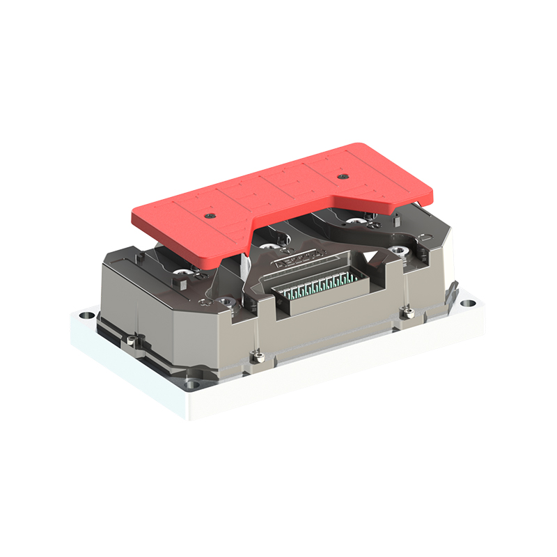
A4 2313 High-Efficiency Brushless DC Motor ControllerFor electric motorcycle or EV drives, this controller pairs FOC vector control with CANBUS, Bluetooth, and Hall or magnetic encoder feedback.View Product →Mechanical fit and environment: where field failures begin
Encoders fail in the field for mechanical reasons more often than electrical ones. Magnetic and inductive types tolerate a defined air gap — commonly 0.5 to 1.5 mm between sensor and magnet — but that gap must survive thermal expansion, bearing play and shock. Shaft runout, axial float and hub eccentricity modulate the signal, and modulated position feedback shows up on the vehicle as torque ripple or speed oscillation. Specify runout limits on the drawing before choosing the sensor, then measure them on the first article instead of trusting the supplier's brochure.
Environment drives technology choice. Optical encoders offer the finest resolution and the least tolerance for dust, oil mist and condensation; an IP67 housing helps, but it does not fix a worn shaft seal. Magnetic encoders survive dust and water yet weaken near high-current cables or large steel structures. For outboard motors and coastal equipment, salt spray and galvanic corrosion make IP67 with marine-rated cable glands a minimum rather than a selling point.
Applications and what each one demands
The same encoder specification produces very different results depending on where the motor sits:
- Electric motorcycles and scooters: low-speed smoothness and hill starts dominate the customer's first impression, so quadrature resolution and electrical angle calibration matter more than top-speed accuracy.
- Robot chassis and automated guided vehicles: odometry error accumulates over a shift, so counts per revolution multiplied by wheel diameter sets the practical navigation budget.
- ATV and UTV drivetrains: mud, water crossings and vibration push the choice toward sealed magnetic feedback with generous air-gap tolerance.
- Electric outboard motors: corrosion resistance and cable integrity decide service life, not resolution alone.
Packaging matters too. Integrated mid-drive units place the sensor inside the gearbox housing, where oil mist and heat are constant neighbours, and where the sensor cannot be swapped without opening the motor. That arrangement rewards early mechanical review and a supplier who understands the whole drivetrain rather than a sensor sold on specifications alone.
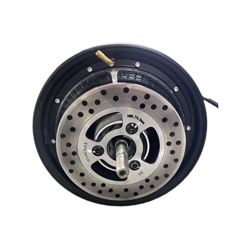
B2B Mid-Drive Motors for E-Bike Drive SystemsReview this B2B mid-drive motor category for factory/supplier options, controller pairing, and after-sales support relevant to integrated e-bike drive systems.View Product →A validation checklist before you release the design
Most encoder problems are discovered late because testing focuses on the datasheet rather than the assembly. Work through these steps before signing off a production release:
- Confirm what the machine must do in the first 200 milliseconds after power-up, and let that answer decide incremental versus absolute.
- Match voltage levels, protocol, supply current and maximum frequency to the actual controller input stage.
- Measure shaft runout, eccentricity and sensor air gap on the first article, not on a bench fixture.
- Run the assembly across the full temperature range and record position error at the extremes.
- Calibrate the electrical angle offset and store it per motor batch, since one misaligned batch produces torque ripple everywhere.
- Verify cable routing and shielding under conducted and radiated noise, with the motor loaded, not idling.
- Request batch-to-batch consistency data and a documented change notification process, because an unannounced magnet or disc revision quietly invalidates your firmware calibration.
A motor encoder is not a component to be bought at the end of a project and bolted on afterwards. Decide the start-up behaviour first, then the resolution the application genuinely needs, then the interface and mechanical envelope that can hold that resolution in the real environment. Verify the combined drive on a loaded bench, and keep the calibration record with the motor batch.
Shanghai APT Power Technology builds brushless DC motor controllers, mid-drive motors and hub motors around exactly that sequence, matching controller firmware to motor characteristics rather than selling hardware in isolation. Whether the application is an electric motorcycle, a robot chassis, an ATV or an electric outboard, position feedback belongs in the first engineering conversation — not in the first warranty claim.
NEXT:How Do Electronic Speed Controllers Work? Inside the ESC's Signal Chain
Interested in cooperation or have questions?

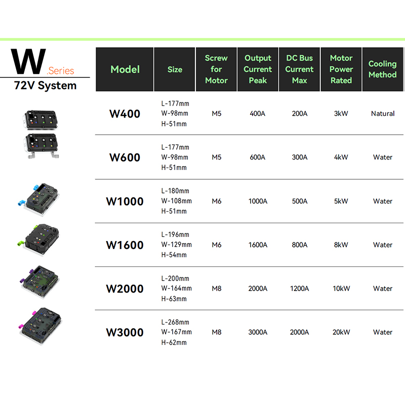

As Custom Permanent Magnet Synchronous Motor Controllers Manufacturers and Permanent Magnet Motor Controllers Suppliers in China, Focusing on the drive control of permanent magnet synchronous motors, we provide a safe and sufficient power source for the electrification of travel vehicles.
- [email protected]
- +86-170 9191 9800
- Room 123A, No. 1000 Ziyue Road, Minhang District, Shanghai, China
Copyright © Shanghai APT Power Technology Co., Ltd.All rights reserved

