 English
 Español
 عربى
عربى
Back Electromotive Force Explained: How Back EMF Shapes Motor Controller Design
Imagine a brushless motor spinning at full speed, then the power stage suddenly switches off. The rotor continues to turn, and the motor terminals still show a voltage. That voltage is back electromotive force, often called back EMF. It is the motor acting as a generator and producing an opposing voltage that limits current flow. For design engineers and procurement teams, back EMF is not a theoretical footnote. It sets the maximum speed, influences commutation timing, and determines how robust a controller must be.
Content
What Is Back Electromotive Force?
Back EMF follows from Faraday’s law of induction. When current flows through a stator winding, it creates a magnetic field. As the rotor moves past that winding, the magnetic flux linking the winding changes, and this change induces a voltage. By Lenz’s law, the induced voltage acts in a direction that opposes the current that produced the motion. The faster the rotor spins, the higher this opposing voltage becomes. The term counter-electromotive force is also used, because the induced voltage literally counters the applied voltage.
In mathematical form, back EMF is E = Ke × ω, where Ke is the back EMF constant and ω is the angular speed. Ke depends on winding turns, magnet strength, and motor geometry. In permanent magnet motors, Ke is usually stated in V/krpm, and it is one of the first values to compare when you pair a motor with a controller.
Why Back EMF Matters in Motor Drive Design
Back EMF affects almost every part of a motor drive. It tells the controller when to switch, how fast the motor can run, and whether sensorless commutation is feasible.
Back EMF and Commutation
In a brushless DC motor, only two of the three phases are energized at any instant. The controller must know when to shift current to the next winding pair. In a sensored design, Hall sensors provide that timing. In a sensorless design, the controller detects the zero-crossing of back EMF on the non-energized phase. At low speed, this signal is small; at high speed, it is strong. That is why sensorless commutation is easy above a few hundred RPM, while starting from standstill requires a different strategy.
Many modern sensorless drives start the motor open-loop and then switch to back EMF detection once the signal is stable. This approach is used in our high-efficiency brushless DC motor controller, which keeps switching efficient across a wide speed range.
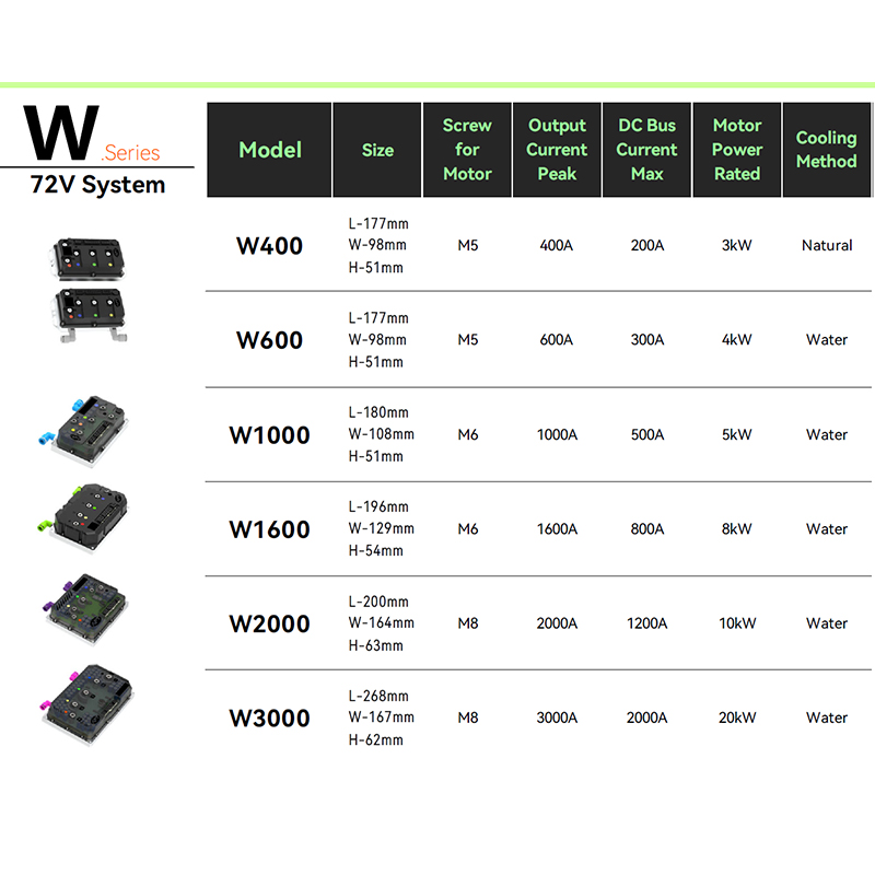 A4 High efficiency Brushless DC Motor Controller Suppliers, Factory - Shanghai AAPT is A4 High efficiency Brushless DC Motor Controller Suppliers and Wholesale A4 High efficiency Brushless DC Motor Controller Factory ...View Product →
Back EMF and Speed Limitation
In a simplified equivalent circuit, the supply voltage equals the winding resistance drop plus the back EMF. As speed increases, back EMF rises and leaves less voltage to push current through the winding. At no load, the motor runs at a speed where back EMF is nearly equal to the bus voltage and current is almost zero. For example, a 48 V motor with a Ke of 10 V/krpm reaches roughly 4,800 rpm at no load before back EMF equals the bus voltage. To go faster, you must raise the bus voltage or reduce Ke. A high-Ke motor is therefore not always preferable, it limits high-speed performance unless the controller can apply field weakening.
Back EMF in Sensorless Control
For permanent magnet synchronous motors, back EMF is sinusoidal. Sensorless control uses an observer to estimate rotor position from the back EMF vector, removing the need for a mechanical sensor. This cuts cost and adds reliability, but the observer must be tuned carefully. During a sudden load change, the back EMF estimate must keep pace with the real signal. A controller with low-latency current loops, such as a fast-response brushless DC motor controller, gives the observer a cleaner signal to follow.
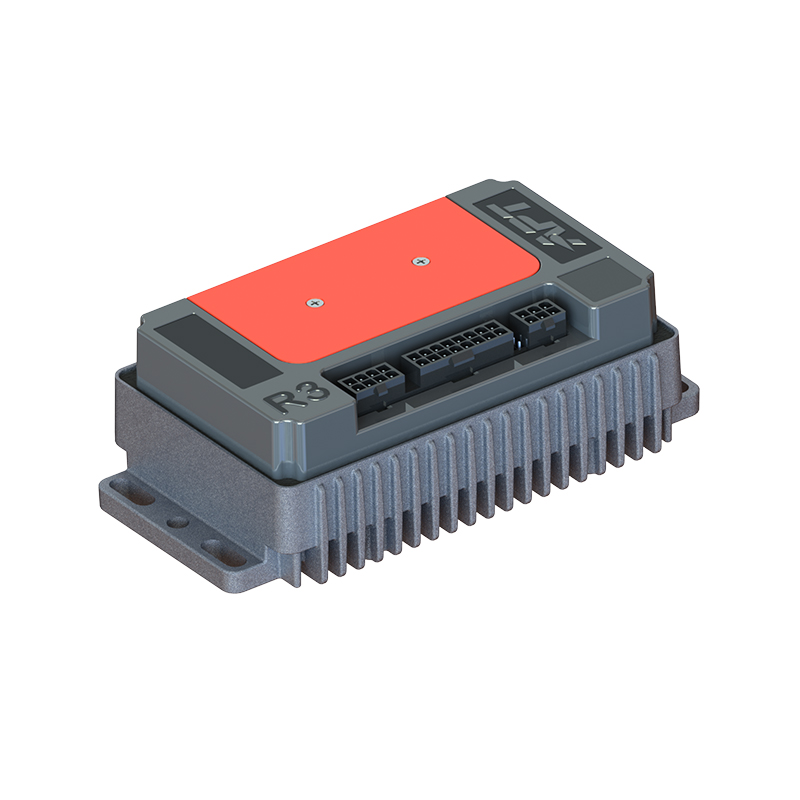
R5 Fast response Brushless DC Motor Controller Suppliers, Factory - Shanghai APTAPT is R5 Fast response Brushless DC Motor Controller Suppliers and Wholesale R5 Fast response Brushless DC Motor Controller Factory in C...View Product →
Understanding the software layer that interprets back EMF is just as important as the hardware. A closer look at the role of software in modern motor controllers shows how drive logic is evolving.
How to Measure Back EMF in Practice
Back EMF is not only a calculated value; it can be measured directly. With an oscilloscope, probe the motor phase with respect to the neutral point, spin the motor, and read the peak voltage. When the motor is driven by a controller, capture the terminal voltage during the PWM off-time to avoid switching noise. Recording the voltage at several speeds gives a linear curve whose slope is Ke.
To measure Ke, rotate the motor at 1,000 rpm and read the peak line-to-neutral voltage. If the scope shows 12 V, Ke is approximately 12 V/krpm for that winding configuration. For line-to-line measurements, divide the reading by √3 to obtain the per-phase value.
| Motor type | Back EMF waveform | Zero-crossing signal | Sensorless difficulty |
|---|---|---|---|
| Brushed DC | Quasi-constant DC | Not required | Low |
| Brushless DC | Trapezoidal | Distinct zero-crossing | Medium |
| PMSM | Sinusoidal | Needs observer | High |
For readers interested in how PMSM drives are evolving, the ongoing advances in permanent magnet synchronous motor technology provide useful context for newer control methods.
Practical Design Considerations for Controller Selection
Voltage Margin and Overvoltage Protection
Every motor controller has a maximum bus voltage rating. During regenerative braking or rapid deceleration, back EMF can push the bus voltage above the supply rail. If the controller has no protection, the bus capacitor or power MOSFETs can be damaged. A well-designed drive either limits regenerated current or dumps excess energy into a resistor. For applications with aggressive speed changes, a high-performance motor controller with dedicated protection logic handles back EMF transients more safely than a generic drive.
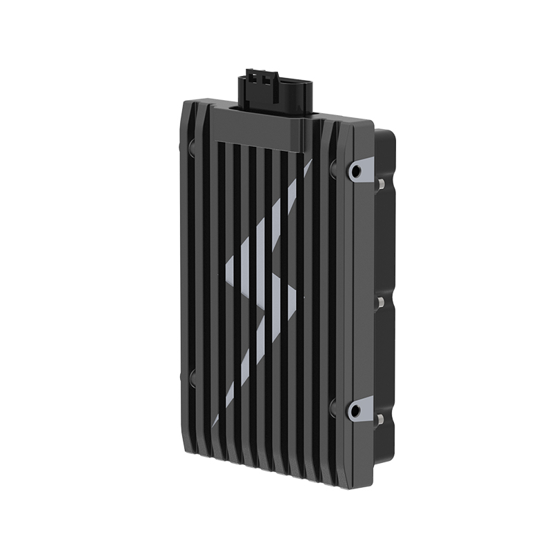
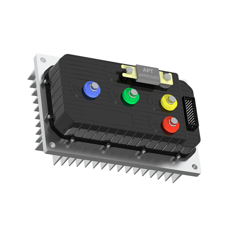
T Series High Performance Motor Controllers Suppliers, FactoryAPT - T300 T400 T500 T720 T1000 T1400 T1800 Permanent Magnet Synchronous Motor Controllers Factory, T Series High Performance Motor Contr...View Product →
Matching the Controller to the Motor
The back EMF constant Ke must match the controller voltage rating and the application speed range. A motor optimized for low-speed torque often has a high Ke, which produces high voltage per RPM. If that same motor must reach high speed, the controller must handle the higher voltage or use field weakening. A low-Ke motor can run faster but draws more current for the same torque. Always compare the rated voltage, Ke, and peak current limits before locking in a pairing.
Temperature further complicates the calculation. Strong magnets lose a small percentage of flux as they heat up, reducing Ke and lowering back EMF. The motor then runs faster at the same voltage, but with less torque per amp. A controller that includes thermal limits can compensate, but the system’s high-speed behavior will still shift.
Conclusion: Back EMF Is a Design Input
Back EMF is not a disturbance to average out; it is a physical signal that reports rotor speed, switching timing, and required voltage margin. When you evaluate a motor controller, ask how it samples back EMF at low speed, at high speed, and during regeneration. The correct motor and controller pairing determines efficiency, reliability, and lifetime.
As a motor drive supplier, Shanghai APT Power Technology builds brushless DC and PMSM controllers around these realities. If you are specifying a new drivetrain, review the motors and controllers in our product range and consider how Ke, bus voltage, and back EMF will interact in your real operating envelope.
NEXT:Speed Control of BLDC Motor: Open-Loop, Closed-Loop & PID Explained
Interested in cooperation or have questions?
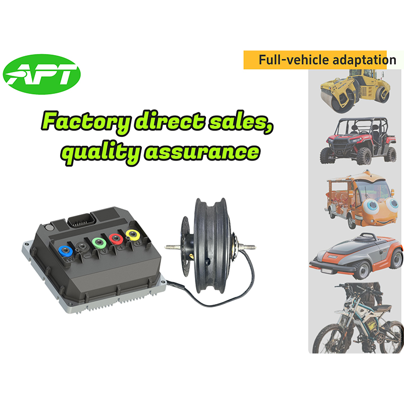


As Custom Permanent Magnet Synchronous Motor Controllers Manufacturers and Permanent Magnet Motor Controllers Suppliers in China, Focusing on the drive control of permanent magnet synchronous motors, we provide a safe and sufficient power source for the electrification of travel vehicles.
- [email protected]
- +86-170 9191 9800
- Room 123A, No. 1000 Ziyue Road, Minhang District, Shanghai, China
Copyright © Shanghai APT Power Technology Co., Ltd.All rights reserved

