 English
 Español
 عربى
عربى
Speed Control of BLDC Motor: Open-Loop, Closed-Loop & PID Explained
Content
- 1 Why BLDC Motors Need Active Speed Control
- 2 Open-Loop Speed Control: PWM Duty Cycle
- 3 Closed-Loop Speed Control: Hall Sensors and Feedback
- 4 PI and PID Control: The Algorithms Behind Closed-Loop Precision
- 5 How Controller Choice Affects Real-World Speed Control Quality
- 6 Matching Controller to Motor for Reliable Speed Control
Why BLDC Motors Need Active Speed Control
A brushed DC motor slows down or speeds up in a fairly direct way — change the voltage across the brushes, and the motor responds. A brushless DC (BLDC) motor doesn't have that luxury. Without brushes and a mechanical commutator, something else has to decide which winding gets energized at which instant, and that same system ends up responsible for speed as well.
That "something else" is the motor controller. It switches current through the three phase windings in the correct sequence to keep the motor turning, and by adjusting how that switching happens, it also sets how fast the rotor spins. Get the control strategy wrong and the motor either can't reach the speed it's asked for, or it hunts and oscillates instead of holding steady — a problem that shows up constantly in hub motors commonly paired with speed-controlled BLDC drives on e-bikes and light EVs, where riders expect the throttle response to feel immediate and linear.
Open-Loop Speed Control: PWM Duty Cycle
The simplest way to control a BLDC motor's speed is open-loop: the controller adjusts the pulse-width modulation (PWM) duty cycle feeding the power transistors, which changes the average voltage applied to the windings, which changes speed. Higher duty cycle, more average voltage, faster spin. No feedback loop checks whether the motor actually reached the requested speed — the controller just commands a duty cycle and trusts the motor to follow.
This approach is common because it's cheap and simple to implement, and Texas Instruments' application guidance on sensored BLDC control notes it works well specifically in systems where the relationship between input and resulting speed is predictable and tight tracking isn't critical. The trade-off shows up under variable load: without feedback, a sudden load increase drags speed down and the controller has no way to know it needs to compensate.
Closed-Loop Speed Control: Hall Sensors and Feedback
Closed-loop control solves that blind spot by adding a feedback signal — usually from Hall effect sensors already present for commutation, sometimes from a dedicated encoder. The controller continuously compares actual speed against the target, calculates the error, and adjusts the PWM duty cycle in real time to close the gap.
Because Hall sensors already report rotor position for commutation purposes, deriving speed from the timing between Hall state transitions adds little extra hardware cost. That makes Hall-based closed-loop control the default choice across most commercial BLDC applications — it holds speed steady as load changes, without needing a separate speed sensor.
PI and PID Control: The Algorithms Behind Closed-Loop Precision
The math inside closed-loop control usually comes down to a PI or PID controller acting on the error between target and actual speed.
A PI (Proportional-Integral) controller combines a proportional term that reacts to the current error with an integral term that accumulates past error over time, which eliminates the small steady-state offset a proportional term alone would leave behind. Adding a derivative term turns it into a full PID controller, which reacts to the rate of change of the error as well — useful for damping overshoot in systems that need to settle on a target speed quickly without oscillating past it.
PI control tends to be the practical default for general-purpose speed regulation because it's simpler to tune and less sensitive to sensor noise than a full PID loop. PID earns its extra complexity in applications like robotics or drones, where fast, precise settling at a new speed matters more than tuning simplicity.
How Controller Choice Affects Real-World Speed Control Quality
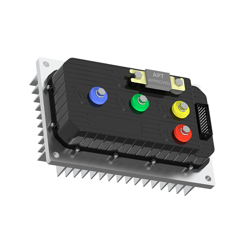
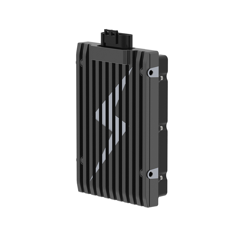
The control algorithm only performs as well as the hardware executing it. A controller with a slow control loop or poor current sensing will still hunt and lag even with well-tuned PID gains, which is why response speed matters as a hardware spec, not just a software one. A fast-response controller tuned for quick speed correction shortens the delay between a load change and the controller's compensating response, which is what actually determines how steady the motor feels under real-world load swings rather than in a clean bench test.
PWM switching frequency and its interaction with the motor windings also affects the audible and mechanical side of speed control — a badly tuned switching scheme can produce whine or vibration that gets worse as duty cycle changes. An ultra-quiet controller that keeps PWM switching noise low at speed addresses that directly, which matters in consumer applications where audible motor noise is as much a complaint driver as raw performance.
Matching Controller to Motor for Reliable Speed Control
Even a well-designed closed-loop controller can't compensate for a mismatch between its current rating, Hall sensor configuration, and the motor it's driving. Pole count, phase resistance, and sensor timing all factor into how cleanly a controller can read feedback and respond, and a mismatched pairing shows up as rough low-speed operation, excess heat, or speed control that never quite settles. Our controller and motor pairing guide covers how to check that a controller's specifications actually fit the motor it's meant to drive before those problems show up in the field.
For readers who want to go deeper into how the control algorithm itself gets implemented in firmware, our deeper look at the software layer behind modern motor controllers covers how these control loops are structured and tuned at the firmware level.
NEXT:Hub-Motor Guide: Types, Efficiency & E-Bike Performance
Interested in cooperation or have questions?
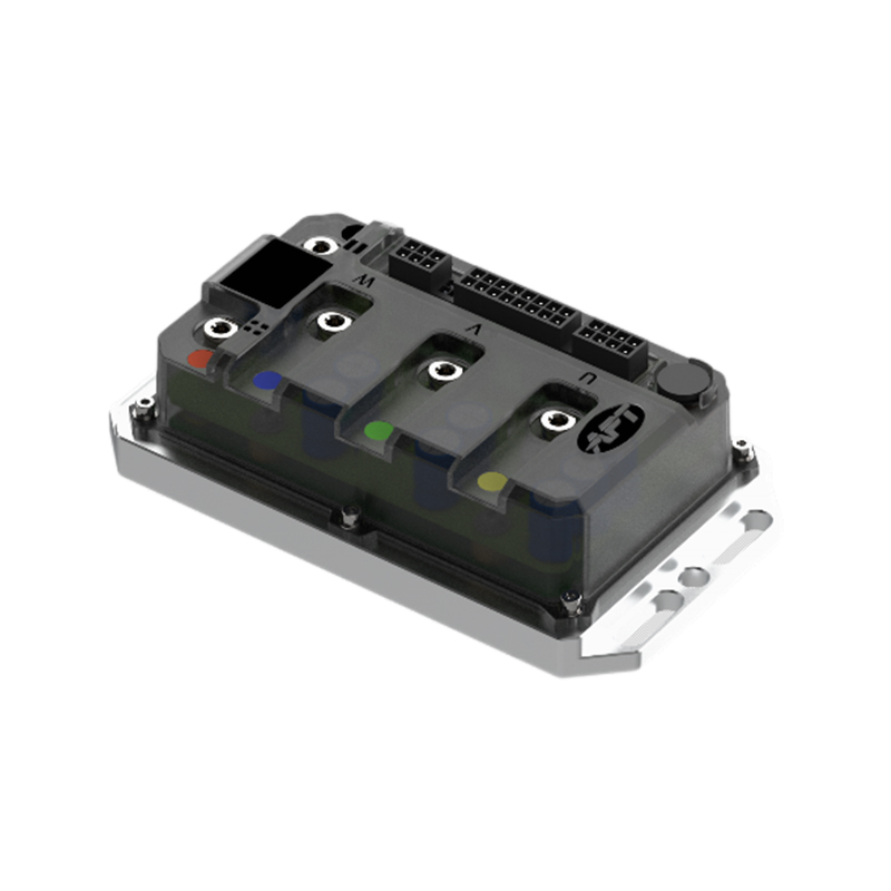
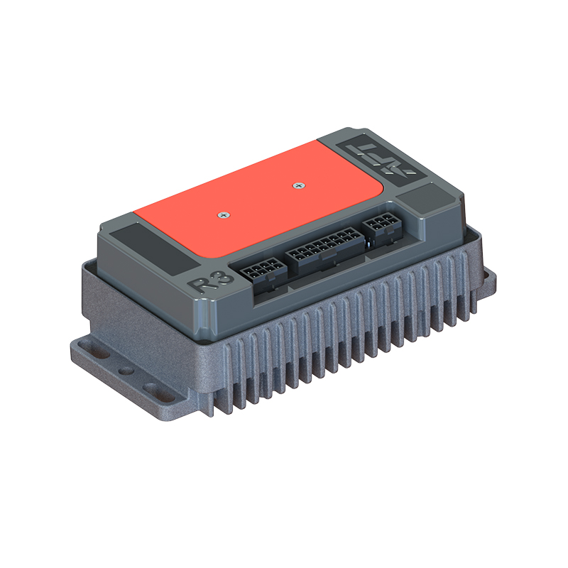
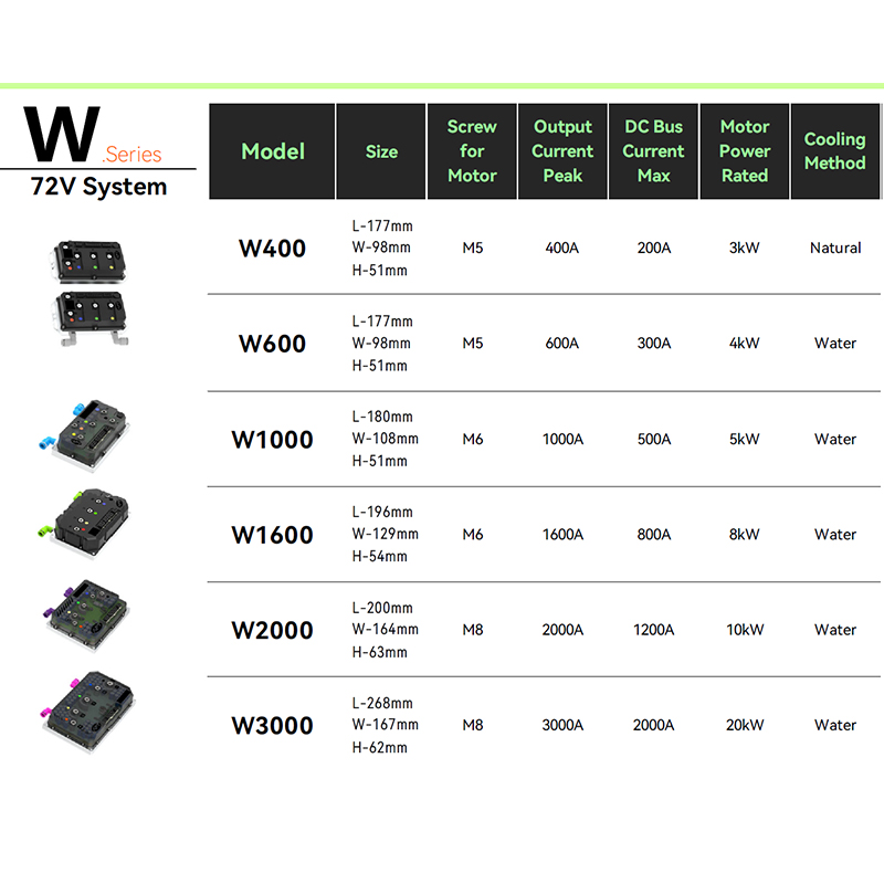

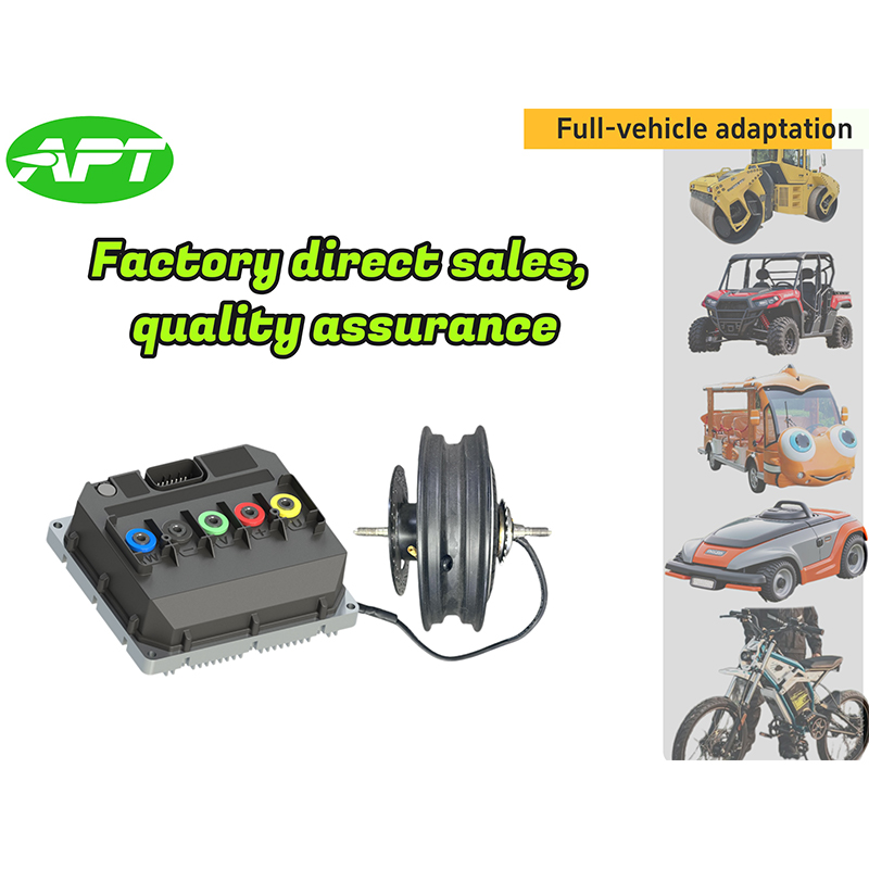

As Custom Permanent Magnet Synchronous Motor Controllers Manufacturers and Permanent Magnet Motor Controllers Suppliers in China, Focusing on the drive control of permanent magnet synchronous motors, we provide a safe and sufficient power source for the electrification of travel vehicles.
- [email protected]
- +86-170 9191 9800
- Room 123A, No. 1000 Ziyue Road, Minhang District, Shanghai, China
Copyright © Shanghai APT Power Technology Co., Ltd.All rights reserved

