 English
 Español
 عربى
عربى
Torque Control Explained: A Practical Guide for BLDC Motor Controller Selection
Picture an electric motorcycle holding position on a steep ramp while carrying a passenger. A speed controller holds a low target speed, yet a small throttle blip can turn a controlled launch into a violent jerk. Now picture a delivery robot crossing a doorway that is slightly too narrow. If the controller keeps pushing at full current, the gearbox absorbs the impact. Both situations are solved by torque control, the operating mode that regulates the rotational force a motor produces rather than its speed or position.
This article is written for engineers and OEM project teams who are evaluating brushless motor controllers for electric motorcycles, robot chassis, electric ATVs, UTVs, and outboard motors. We will explain what torque control actually means in a BLDC or PMSM drive, how the controller achieves it, and which specifications determine whether the torque feels smooth and responsive in real-world operation.
Content
What Torque Control Actually Means
Torque control regulates the current delivered to the motor so that the shaft torque follows the command given by the rider, driver, or motion controller. It does not hold a target speed. It does not hold a rotor position. The motor simply produces whatever speed results from the applied torque and the load attached to the shaft.
A simple comparison helps. When you push a hand cart, your arms apply force, and the cart moves at whatever speed that force produces against rolling resistance and slope. Your arms are performing torque control. If you locked the cart speed instead, that would be speed control.
| Control mode | Regulated variable | Typical command source | Primary use cases |
|---|---|---|---|
| Speed control | Motor RPM | Throttle, potentiometer, CAN setpoint | Cruise operation, conveyors, fans, pumps |
| Position control | Rotor angle | Encoder feedback, step or direction pulses | Steering, valves, robotic joints |
| Torque control | Motor current, and therefore torque | Analogue input, CAN torque command, pedal | Traction, tensioning, force-limited motion |
Torque control is also a protective function. A controller programmed to deliver no more than 15 Nm simply will not output 20 Nm, even if the driver demands it. Wheel slip on loose gravel, a blocked actuator, or a partially seized bearing no longer translates directly into driveline stress. This is why torque limiting is frequently used as a safety function in motion systems.
How a Brushless Controller Delivers Controlled Torque
In a brushless DC motor or a permanent magnet synchronous motor, torque is proportional to the armature current in the quadrature axis. Torque control is therefore current control. A well-designed controller measures the phase currents, compares the torque-producing component against the torque command, and adjusts the inverter switching pattern to reduce the error. This inner current loop is where torque control actually lives.
Field-Oriented Control and the Current Loop
Field-oriented control, commonly called FOC, transforms the measured three-phase currents into two components in a rotating reference frame: a magnetizing component on the d-axis and a torque-producing component on the q-axis. The controller commands the q-axis current to match the requested torque and keeps the d-axis current near zero for a surface-mount PMSM. The bandwidth of this current loop decides how quickly torque corrections happen. A loop updated at 10 to 20 kHz reacts to load changes in a few milliseconds, which is the difference between a stable crawl and a stuttering motion at low speed. FOC is a central reason permanent magnet synchronous motor technology continues to improve for traction applications: the same hardware delivers smoother torque, higher efficiency, and regenerative braking through software changes alone.
Sensor Feedback and Sensorless Operation
Torque control quality depends heavily on rotor position feedback. Hall sensors provide coarse, 60-degree resolution, which is enough for trapezoidal commutation but not for smooth torque at low speed. Encoders and resolvers provide continuous rotor angle, allowing FOC to hold precise torque even near standstill. Sensorless algorithms estimate rotor position from back-EMF, which removes the sensor cost but cannot maintain full torque at zero speed where no back-EMF exists. Many production drives use a hybrid strategy: sensor-based starting and sensorless running above a few hundred RPM.
Phase current sensing is equally important. Low-side shunt resistors are inexpensive but noise-sensitive; integrated phase sensors cost more and deliver cleaner measurement at low currents. The sampling frequency and filtering of the current signal set the practical torque ripple seen on the shaft, so torque figures in a datasheet should be read together with the sensing architecture used in the controller.
Why Torque Control Matters in Real Applications
Torque control changes measurable behaviour in every major application category in electric mobility and robotics.
- Electric motorcycles. Controlled launches on slopes, wheel-slip prevention on wet asphalt, and regenerative braking that applies negative torque in a smooth ramp. Without torque limits, the motor can engage violently when the rider twists the throttle.
- Robot chassis. Torque limiting protects gears and motors during collisions. When an autonomous mobile robot drives into an unexpected obstruction, the controller caps current instead of feeding full power into the drivetrain.
- Electric ATVs and UTVs. Low-speed crawling on uneven terrain requires precise low-torque output. A speed-controlled system tends to surge when the wheels lose and regain traction.
- Electric outboard motors. Constant thrust against current and wind requires the controller to respond to load changes faster than a speed loop can.
The multi-scenario adaptation of motor drive products reflects exactly this demand: one controller platform must handle a wide range of torque commands, from small robot wheels to large ATV drivelines.
Key Specifications That Determine Torque Quality
When sourcing a controller for a torque-sensitive application, continuous current rating and peak current are only the starting point. The following specifications have an outsized influence on torque behaviour.
- Current loop update rate. A higher update rate, typically 10 to 20 kHz, shortens the delay between a torque command change and the actual torque change on the shaft.
- PWM frequency. A higher switching frequency reduces current ripple and audible noise but increases switching losses. Controllers aimed at quiet operation choose a frequency that balances both.
- Current sensing resolution and noise. The smallest measurable current step sets the smallest torque step. A noisy sensing circuit produces torque chatter at low load.
- Torque ripple. Low torque ripple keeps rotation smooth at low speed, which matters for robot joints and propellers.
- Overload capability. Transient torque peaks for hill starts and obstacle handling usually exceed the continuous rating. Check the overload curve against the real duty cycle.
- Thermal behaviour. Sustained torque is set by the thermal design of the controller. A controller that throttles early will silently reduce available torque during extended operation.
Component quality matters beyond the numbers. A torque-controlled drive switches phase current hundreds of times per second, and any intermittent resistance in connectors or solder joints appears as current measurement noise that becomes torque chatter. This is why the material quality of the hardware is a legitimate engineering specification, not only a marketing claim.
It is also worth verifying datasheet torque ripple figures with the actual motor during prototype testing. Manufacturers measure torque ripple under controlled conditions that may not match a production frame, a specific winding inductance, or the PWM frequency a project plans to use. A short bench test that logs torque at several speed points will reveal most of the issues that later become field complaints.
Matching the Controller to the Motor and the Duty Cycle
Torque control performance is a system property, not a controller property in isolation. The current loop is tuned to the motor winding inductance and resistance. Connect the same controller to a motor with different parameters and the torque response can become oscillatory or sluggish. This is why pairing the controller and motor as part of the system design matters more than selecting either component alone.
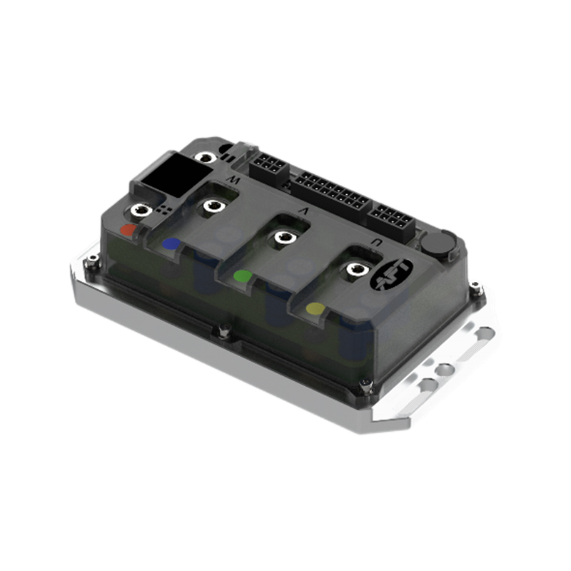
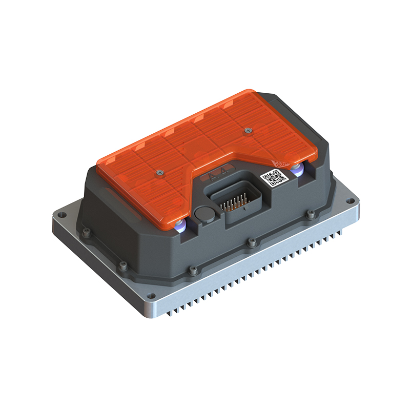
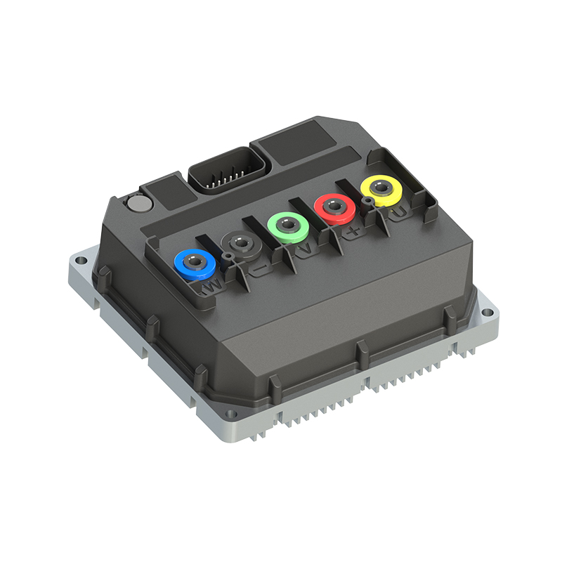
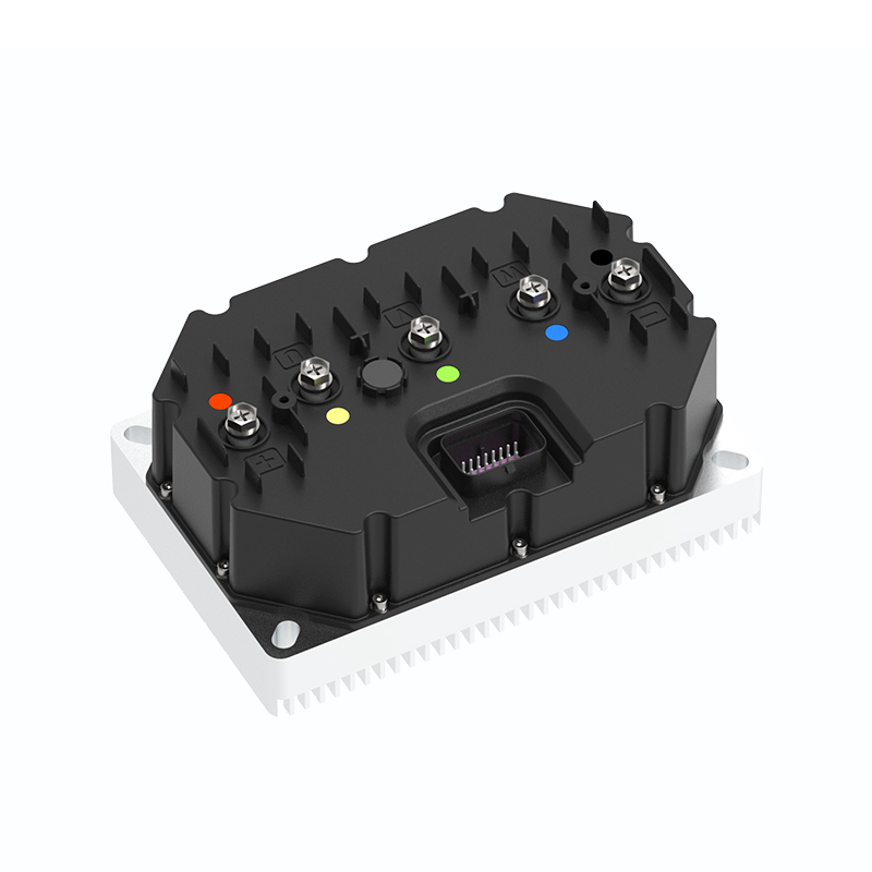
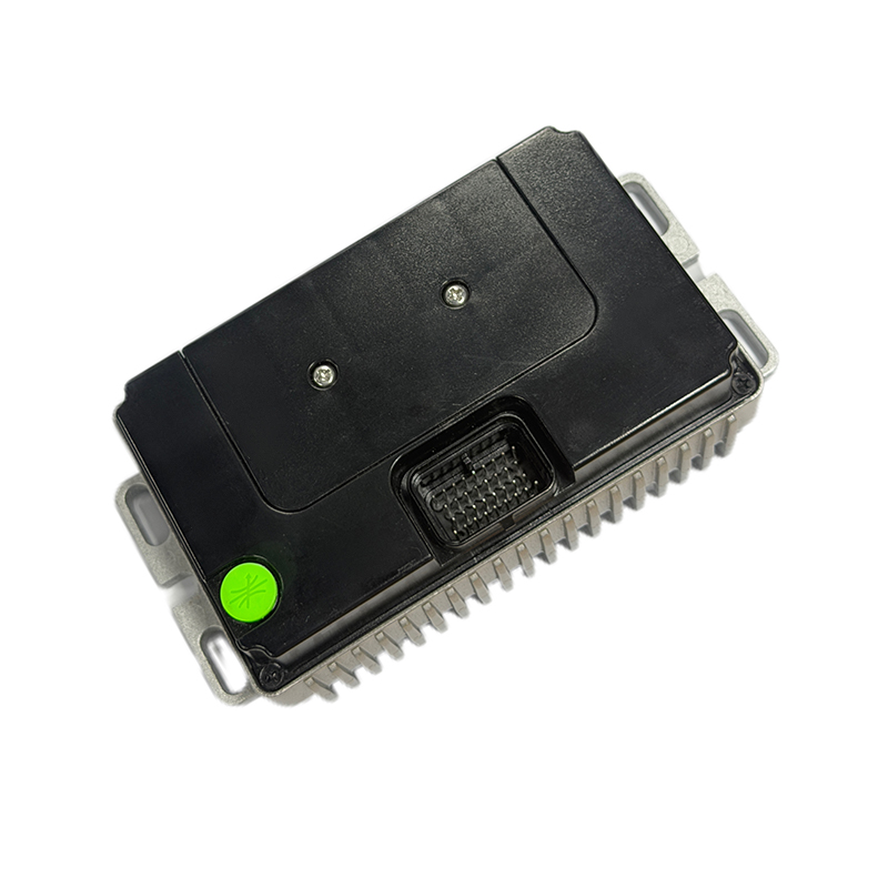
For applications that need fast torque response, the R5-2215 fast-response brushless DC motor controller is designed to minimize the delay between the torque command and the mechanical shaft torque. For efficiency-sensitive platforms such as urban electric motorcycles, the A4-2313 high-efficiency brushless DC motor controller holds torque precisely while reducing electrical losses. For high-voltage, high-power architectures with dynamic torque demands, the T-series high-performance motor controller covers the wider envelope that ATVs, UTVs, and larger robot platforms typically require.
 T Series High Performance Motor Controllers Suppliers, FactoryAPT - T300 T400 T500 T720 T1000 T1400 T1800 Permanent Magnet Synchronous Motor Controllers Factory, T Series High Performance Motor Contr...View Product →
 A4 High efficiency Brushless DC Motor Controller Suppliers, Factory - Shanghai AAPT is A4 High efficiency Brushless DC Motor Controller Suppliers and Wholesale A4 High efficiency Brushless DC Motor Controller Factory ...View Product →
 R5 Fast response Brushless DC Motor Controller Suppliers, Factory - Shanghai APTAPT is R5 Fast response Brushless DC Motor Controller Suppliers and Wholesale R5 Fast response Brushless DC Motor Controller Factory in C...View Product →
Software plays a central role here. Torque ramp shaping, current loop tuning, and fault behaviour are configured in firmware, so the same hardware can be tuned for a cargo e-bike, a wheelchair, or a marine drive. The shift of torque management into software is one of the themes of a detailed article on the role of software in modern motor controllers.
Conclusion
Torque control is not a single component or algorithm. It runs through the current sensing chain, the rotor position feedback, the current loop firmware, the inverter stage, and the physical connector quality. For OEMs building electric vehicles and mobile machines, the ability to regulate torque smoothly determines whether the product feels predictable and refined under real loads. Evaluating current loop bandwidth, torque ripple, overload behaviour, and software configurability during the controller selection phase is the most direct way to avoid drivability re-engineering later in the project.
NEXT:Back Electromotive Force Explained: How Back EMF Shapes Motor Controller Design
Interested in cooperation or have questions?


As Custom Permanent Magnet Synchronous Motor Controllers Manufacturers and Permanent Magnet Motor Controllers Suppliers in China, Focusing on the drive control of permanent magnet synchronous motors, we provide a safe and sufficient power source for the electrification of travel vehicles.
- [email protected]
- +86-170 9191 9800
- Room 123A, No. 1000 Ziyue Road, Minhang District, Shanghai, China
Copyright © Shanghai APT Power Technology Co., Ltd.All rights reserved

