 English
 Español
 عربى
عربى
Closed Loop Motor Control: How Feedback Improves Motor Performance and Reliability
An electric motorcycle that stutters when pulling away from a standstill, a robot chassis that overshoots its target position, an ATV that loses traction response on a steep climb: these symptoms usually trace back to the same root cause. The motor is being told what to do, but it never reports what actually happened. Closed loop motor control closes that gap. It continuously measures the motor's speed, position, or current and adjusts the drive signals in real time so the motor follows the commanded value despite load changes, temperature drift, and component tolerances. For engineers building electric vehicles, robotic platforms, or marine drives, the important question is not whether to use closed loop control, but how well the controller implements it.
Content
What Is Closed Loop Motor Control?
Closed loop motor control, also called feedback control, compares the actual motor output with a reference command and corrects the difference. The essential elements are the reference, a feedback sensor, an error calculation, and a controller that produces the correction. In a brushless motor system, the controller reads phase currents, speed, and sometimes rotor position; the control algorithm then adjusts the PWM signals delivered to the inverter so the measured value converges to the command.
In practice, most controllers use a proportional-integral-derivative (PID) structure or a variant of it. The proportional term reacts to the present error, the integral term removes steady-state error, and the derivative term anticipates changes. Tuning these gains determines whether the system is stable, responsive, or oscillatory. This is fundamentally different from an open loop system, where the controller sends a fixed command and trusts that the motor will respond correctly. Open loop works when the load is predictable and precision is not critical. It fails when friction, inertia, or supply voltage changes unexpectedly.
Open Loop vs. Closed Loop: What Actually Changes
The practical difference shows up in motion quality. A closed loop system corrects errors within milliseconds; an open loop system simply lives with them. For applications that carry people or handle costly payloads, that difference determines whether the product feels precise and safe or rough and unpredictable.
| Aspect | Open Loop | Closed Loop |
|---|---|---|
| Feedback | None | Current, speed, or position sensor |
| Accuracy | Depends on motor and load matching | Maintained under varying conditions |
| Disturbance response | No correction | Active correction in real time |
| Low-speed behavior | Torque drops and becomes uneven | Stable torque down to zero speed |
| System cost | Lower | Higher, but justified by performance |
| Typical applications | Fans, pumps, simple conveyors | Electric vehicles, robotics, servo axes |
The table simplifies a range of trade-offs. A sensorless closed loop design can deliver many closed loop benefits without an encoder, which changes the cost comparison significantly. The control architecture matters more than the label.
The Control Loops Inside a Motor Controller
In a modern brushless motor controller, closed loop control is not a single loop. It is a cascade of loops, each regulating a different physical quantity.
Current Loop
The current loop is the innermost and fastest loop. It regulates the phase currents in the motor windings, which directly sets torque. A fast current loop with a high update rate produces smooth torque at low speed and quiet operation at high speed.
Speed Loop
The speed loop sits above the current loop. It compares measured speed with the reference and generates the current command. This loop handles acceleration, deceleration, and speed stability under changing load.
Position Loop
The position loop is the outermost loop, used when the application needs precise stopping or path following, such as robot joints and steering actuators. It commands the speed loop based on the position error.
The cascade arrangement matters because each inner loop must be faster than the loop around it. If the current loop is slow, the speed loop cannot make the motor feel stiff, and the position loop will overshoot.
| Loop | Regulated quantity | Typical role |
|---|---|---|
| Current loop | Phase current / torque | Fast torque response, smoothness |
| Speed loop | Angular speed | Speed stability under load |
| Position loop | Rotor angle | Precise positioning and path control |
Sensor-Based vs. Sensorless Closed Loop
Closed loop motor control can be implemented with physical sensors or without them. Hall sensors, encoders, and resolvers report rotor position directly. Sensorless control, common in field-oriented control of permanent magnet synchronous motors, estimates rotor position from measured currents and voltages using a motor model. The trade-off is clear: sensorless systems reduce cost and wiring and remove a point of failure, while sensor-based systems maintain higher torque accuracy at very low speed and during standstill. If the application must hold torque at standstill or creep at very low speed, an encoder or Hall sensors are usually required. If the duty cycle spends most of its time above a few percent of rated speed, sensorless algorithms based on back-EMF observation are accurate and cheaper. For electric motorcycles and marine outboards, modern sensorless algorithms provide enough dynamic performance for most operating conditions, as covered in our discussion of permanent magnet synchronous motor technology.
What to Look for in a Closed-Loop Controller
When evaluating a controller for a closed loop application, focus on the implementation rather than the label. The following points separate a well-designed controller from a generic one.
- Current loop bandwidth: a higher bandwidth means faster torque response and better stiffness against load disturbances.
- Control cycle time: short cycle times, typically tens of microseconds, let the current loop react quickly to transients.
- Autotuning: a controller that measures motor parameters and sets loop gains automatically saves hours of manual tuning.
- Field weakening: extends the speed range beyond base speed, essential for high-speed motorcycles and outboards.
- Protection and diagnostics: overcurrent, overtemperature, and stall detection protect both the controller and the motor.
- Software tools: live current, speed, and fault data speed up integration and troubleshooting.
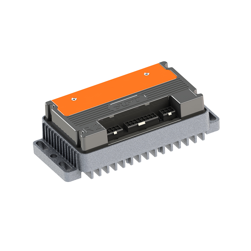
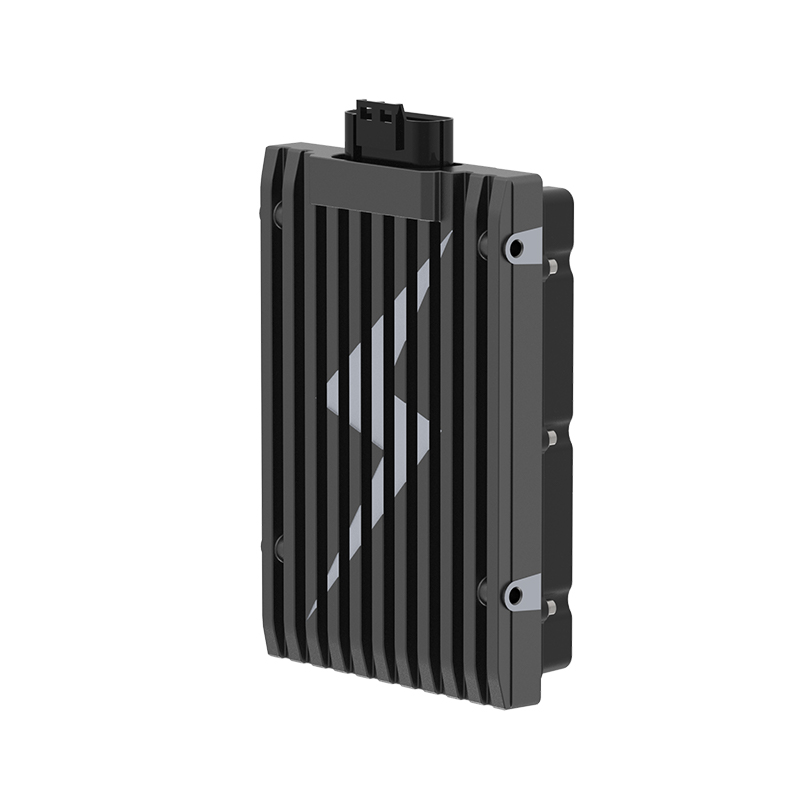
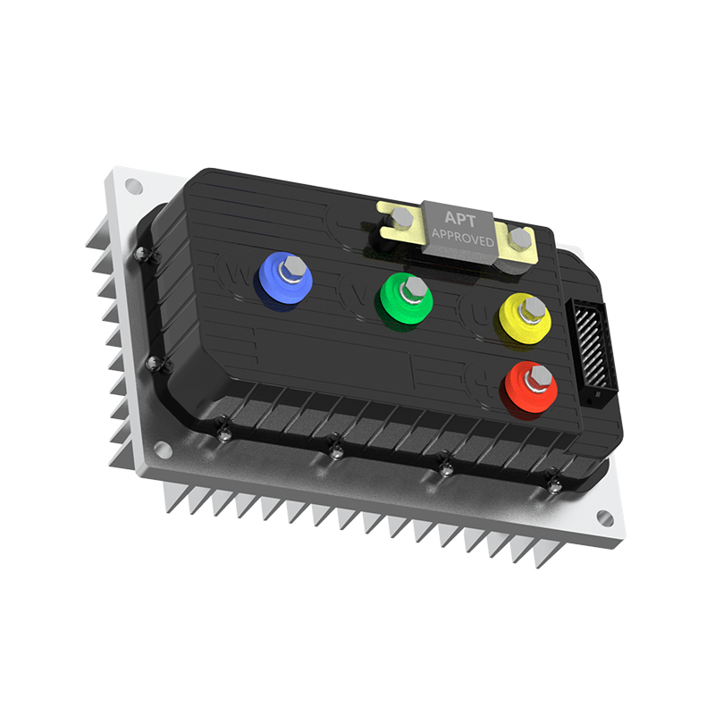
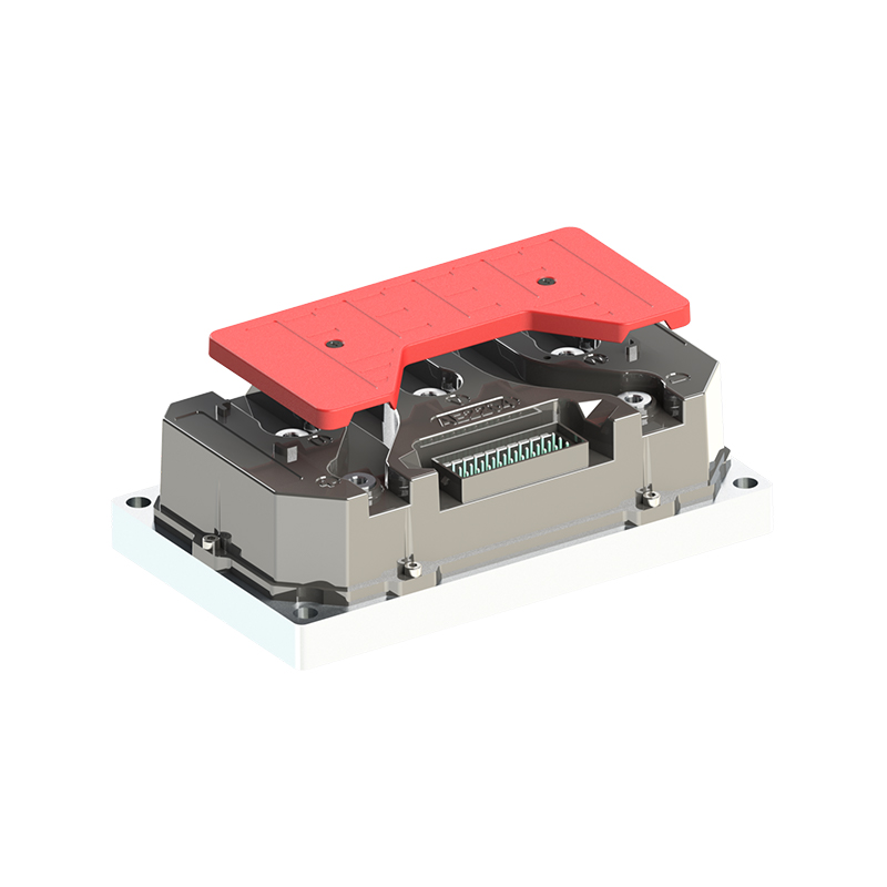
For applications that demand immediate response to changing torque, a controller with fast current loop execution makes a measurable difference. The R5-2215 fast response controller is designed for such duty cycles, where every millisecond of delay translates into motion error. On the reliability side, the A8-2209 high stability controller emphasizes consistent behavior under thermal and electrical stress. When energy efficiency is the priority, the A4-2313 high efficiency controller reduces losses in the inverter stage and extends battery range.
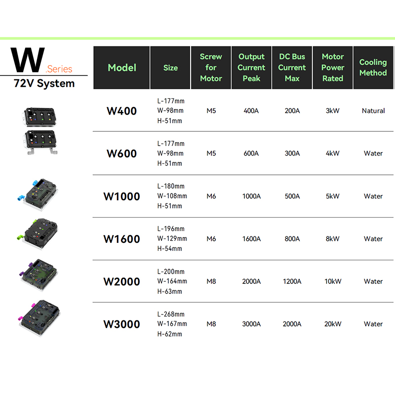 R5 Fast Response Brushless DC Motor Controller for Dynamic Torque ApplicationsThis controller is highlighted for duty cycles where quick current loop response reduces motion error. It suits electric motorcycles, robot chassis, and similar applications needing immediate torque reaction.View Product → A8 High Stability Brushless DC Motor Controller for Reliable Operation Under StressThis model prioritizes consistent performance under thermal and electrical stress, making it a dependable choice for applications that require steady operation in demanding conditions.View Product →
  A4 High Efficiency Brushless DC Motor Controller for Extended Battery RangeThis controller focuses on reducing inverter-stage losses, which helps extend battery range. It is presented as the efficiency-oriented option alongside fast response and high stability models.View Product →
Matching the Controller to the Application
The same closed loop principles apply across industries, but the weighting of each performance factor changes with the use case.
- Electric motorcycles need stable low-speed torque for launches, hill starts, and regenerative braking.
- Robot chassis builds demand precise position and smooth velocity control to avoid overshoot and vibration.
- ATV and UTV applications require robust disturbance rejection because the load on each wheel changes constantly.
- Electric outboards benefit from sensorless operation because the motor sits in a wet, vibration-prone environment where encoders are a weak point.
Each of these applications also depends on the controller being matched to the motor's electrical parameters. A controller with the right voltage class and current rating, paired with a motor whose inductance and back-EMF constants suit the drive, will perform far better than a mismatched pair even with excellent software.
Final Thoughts
Closed loop motor control is what turns a spinning rotor into a precise, responsive actuator. The value is not in the feedback alone; it is in the loops, the tuning, and the protection that surround the feedback. When you choose a motor controller, evaluate its current loop performance, its tuning tools, and its track record in applications close to yours. Those factors, more than any datasheet claim, determine how well your product will perform.
NEXT:Brushless Motor with Hall Sensor: What It Does and When You Need It for Your Project
Interested in cooperation or have questions?



As Custom Permanent Magnet Synchronous Motor Controllers Manufacturers and Permanent Magnet Motor Controllers Suppliers in China, Focusing on the drive control of permanent magnet synchronous motors, we provide a safe and sufficient power source for the electrification of travel vehicles.
- [email protected]
- +86-170 9191 9800
- Room 123A, No. 1000 Ziyue Road, Minhang District, Shanghai, China
Copyright © Shanghai APT Power Technology Co., Ltd.All rights reserved

