 English
 Español
 عربى
عربى
Brushless Motor with Hall Sensor: What It Does and When You Need It for Your Project
When a brushless DC motor datasheet lists "with hall sensor," that line changes more than the price. It changes how the motor starts from standstill, how it delivers low-speed torque, and which controllers can drive it. For anyone selecting a motor for an electric scooter, a robot platform, an ATV, or a marine drive, the hall sensor decision is one of the first system-level calls to make.
The short answer: a brushless motor with hall sensor gives the controller exact rotor position from zero speed, so the motor starts with full torque in the correct direction and runs smoothly at low speed. The trade-off is extra wiring and a controller designed to read Hall signals. When the motor and controller are defined together, that trade usually favors sensored operation.
Content
What a Hall Sensor Does in a Brushless Motor
Inside a brushless DC motor, there is no commutator to switch the windings. The controller has to energize the three phases in a sequence that follows the rotor, and the timing depends on knowing the rotor position at every instant. Hall effect sensors supply that information.
A typical sensored motor contains three Hall ICs mounted at 120 electrical degrees apart. As the rotor magnets pass, each sensor detects the change between north and south poles and switches its output. The three outputs form a 3-bit pattern with six valid states, each corresponding to one 60-degree commutation step. If the controller ever reads a 000 or 111 state during rotation, that is usually a wiring fault, because those states should not appear with a correct Hall pattern.
The Hall sensor is a signal device, not a power device. It does not carry the phase current; it only reports rotor position to the controller. That is why the motor controller is where the real decision-making happens. The same motor can start softly or abruptly, efficiently or wastefully, depending on how the controller processes the Hall pattern.
Why Hall Sensors Matter at Standstill and Low Speed
Sensorless brushless controllers read rotor position from back-electromotive force (BEMF). BEMF rises with motor speed; at standstill it is zero, and below roughly five to ten percent of rated speed it is too small to measure reliably. So a sensorless start uses an open-loop sequence: align the rotor, then ramp it up until BEMF is readable.
That sequence is the weak link. Under load, an align-and-ramp start can produce a current spike, a brief backward jerk, or a stall. The typical symptom is a motor that clicks or hesitates before moving. For an e-bike starting on a slope, a robot lifting a payload, or an electric ATV pulling away on loose ground, that hesitation is unpleasant and hard on the drivetrain.
A hall-sensored motor eliminates the blind phase. The controller knows the rotor position at standstill and applies torque in the right direction immediately. Applications that start and stop frequently, such as delivery robots, pedal-assist bicycles, mobility scooters, and electric motorcycles, benefit most. The controller can also keep that start quiet; an ultra-quiet PWM strategy suppresses the switching noise that often accompanies low-speed operation, so a sensored start feels smooth and silent in premium products.
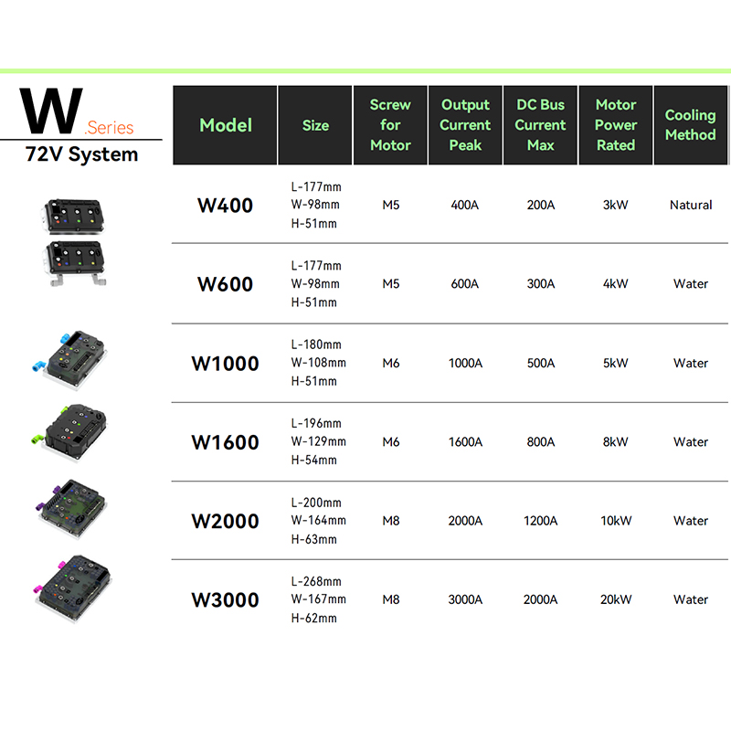 A6 Ultra-quiet Brushless DC Motor Controller for Frequent Stop-and-Go UseThis sensored controller enables smooth, silent starts at standstill, making it well suited for city commuting, cargo duty, and low-speed maneuvering where rotor position feedback is essential.View Product →
| Operating aspect | Sensored (Hall) | Sensorless (BEMF) |
|---|---|---|
| Rotor position at standstill | Known from Hall pattern | Not measurable |
| Startup under load | Direct torque in the correct direction | Align-and-ramp sequence; stall risk |
| Low-speed torque | Stable and repeatable | Limited below roughly 5-10% rated speed |
| Wiring | Three phase leads plus five Hall leads | Three phase leads only |
| Cost and complexity | Extra sensors, connector pins, pull-ups | No additional motor hardware |
| Typical applications | E-mobility, robotics, reversing drives | Fans, pumps, high-speed spindles |
This is why sensored versions are common in hub motor drives for city vehicles; stops, loaded starts, and low-speed maneuvering are exactly the conditions where BEMF falls short. Hub motor performance data from real-world riding conditions follows the same pattern, from stop-and-go commuting to long cargo shifts.
Hub motor performance guides consistently show that sensored versions handle urban duty more predictably than sensorless ones.
Hall Output Types, Voltage Levels, and Commutation Patterns
Hall sensors come in two output formats. Open-collector outputs pull the signal low and need pull-up resistors on the controller side to return high. Push-pull outputs drive the line high and low directly. If the controller board has no pull-ups, an open-collector motor produces no valid high level and the controller never completes its commutation table.
Voltage compatibility also matters. Older motors often use 5V Hall ICs, while many current controller inputs run at 3.3V logic. Feeding a 5V signal into a 3.3V-only pin can damage the input or cause sporadic faults. The motor specification should state the Hall supply voltage and output level; if it does not, ask before ordering.
The spacing between Hall sensors follows one of two standards: 60 electrical degrees or 120 electrical degrees. The controller's commutation table must match this spacing. A motor built for 60° produces a different Hall pattern from a 120° motor, and applying the wrong table causes rough running, torque loss, or loss of synchronization.
Remember also that electrical degrees are not mechanical degrees. A motor with four pole pairs repeats its Hall pattern four times per mechanical revolution. The pole-pair count changes the electrical frequency the controller must handle, so it has to be configured correctly alongside the commutation angle.
Matching a Hall-Sensored Motor with a Controller
A sensored motor only delivers its advantages when the controller is built to read Hall signals. Three checks cover most of the compatibility surface. First, verify the Hall supply voltage and logic level against the controller input rating. Second, confirm the controller supports the motor's commutation angle, 60° or 120°. Third, decide what happens at higher speed; many controllers use Hall signals at low speed and blend into BEMF mode above a threshold, and that transition should be smooth enough to avoid a torque dip.
For an e-mobility powertrain, efficiency in the low-speed operating range is often the largest contributor to real-world range. Sensored commutation keeps the stator current aligned with the rotor, reducing copper loss and heating. A controller that reads Hall inputs correctly, such as the A4-2313 high-efficiency brushless DC motor controller, allows the same motor to be tuned for city commuting, cargo duty, or off-road torque because the commutation curve lives in software.
A4 High-efficiency Brushless DC Motor Controller with Hall InputDesigned to keep stator current aligned with the rotor at low speeds, this controller improves real-world range and can be tuned for different duty cycles from city riding to cargo or off-road.View Product →
When a motor and a controller come from different suppliers, Hall parameters are the first source of mismatch. A 60° motor connected to a controller configured for 120° will run roughly or not at all. A structured pairing scheme settles this before hardware arrives: voltage class, current rating, Hall output format, supply voltage, commutation angle, and pole-pair count are all documented on one page.
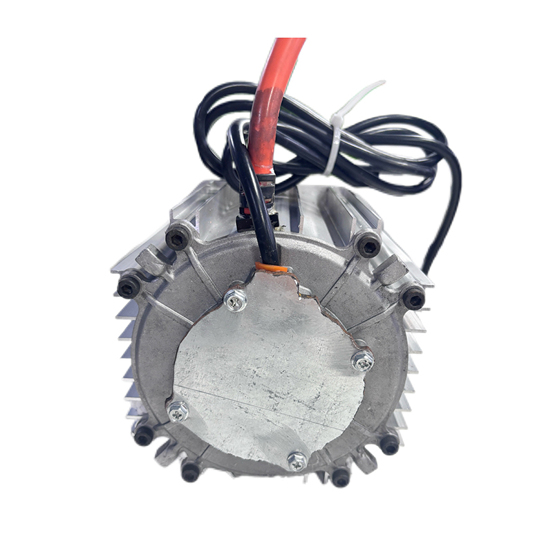 Controller and Motor Pairing Scheme with Six Key ParametersA structured pairing page documents voltage class, current rating, Hall output format, supply voltage, commutation angle, and pole-pair count to prevent mismatches before hardware arrives.View Product →
What to Check Before You Spec a Sensored Motor
Put these six items on one page before you order:
- Hall supply voltage and logic level: match the motor's Hall IC to the controller's input rating.
- Output format: open-collector needs pull-ups on the controller side; push-pull does not.
- Commutation spacing: 60° or 120°, and make sure the controller configuration matches.
- Pole-pair count: verify it and enter it correctly, because it sets the electrical frequency.
- Connector pinout: standard sensored wiring is three phase leads plus five Hall leads (5V, GND, A, B, C). One swapped pin is the most common bench-test failure.
- Hall fault strategy: check whether the controller can detect a stuck or missing Hall signal and fall back to sensorless mode.
A brushless motor with hall sensor is a proven way to make low-speed torque deterministic. The cost is extra wires and a controller with Hall input support. For vehicles and machines that start under load, run at low speed, or reverse frequently, that cost buys smoother behavior and a shorter development cycle. When the Hall parameters are written down and matched against the controller, the sensored motor simply behaves the way the datasheet promised.
NEXT:Brushless Motor Benefits: Efficiency, Longevity, and Precise Speed Control
Interested in cooperation or have questions?
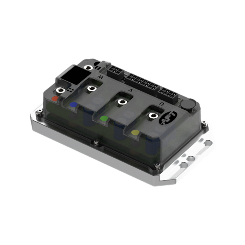
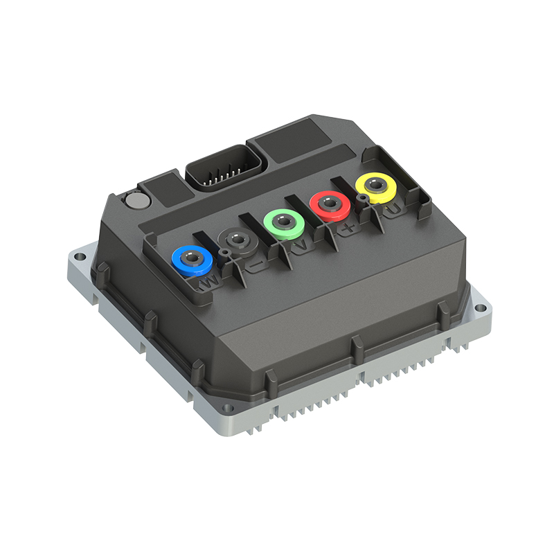
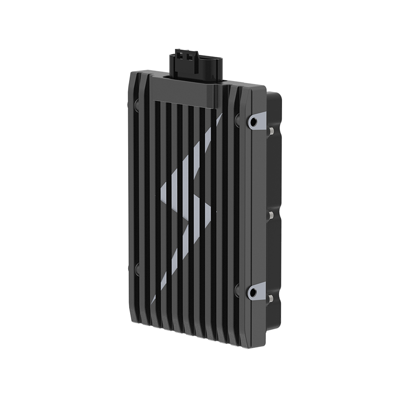
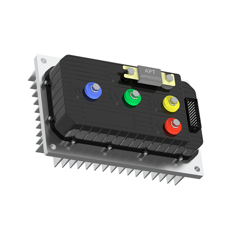
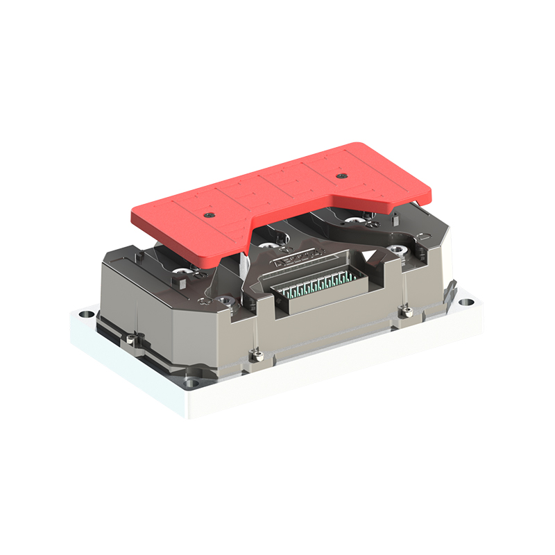
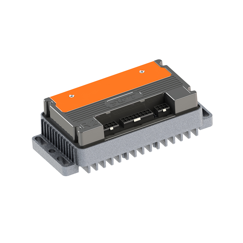

As Custom Permanent Magnet Synchronous Motor Controllers Manufacturers and Permanent Magnet Motor Controllers Suppliers in China, Focusing on the drive control of permanent magnet synchronous motors, we provide a safe and sufficient power source for the electrification of travel vehicles.
- [email protected]
- +86-170 9191 9800
- Room 123A, No. 1000 Ziyue Road, Minhang District, Shanghai, China
Copyright © Shanghai APT Power Technology Co., Ltd.All rights reserved

