 English
 Español
 عربى
عربى
Motor Control Algorithms: Six-Step, FOC, and Sensorless Methods Explained
A specification sheet can tell you that a motor controller handles 48 V and 60 A, but it will not tell you how the motor sounds at walking speed, how much torque ripple your robot chassis will feel, or whether the motor can still pull away on a steep hill. Those behaviors are decided by the motor control algorithm embedded in the firmware. Three families dominate brushless DC (BLDC) and permanent magnet synchronous motor (PMSM) control: six-step commutation, field-oriented control (FOC), and sensorless observer methods. For most new vehicle and automation programs, FOC with a sensorless observer is the practical default, while six-step remains a low-cost choice for simple loads. The sections below explain how these algorithms differ and what that difference means when you select a controller.
Content
What Motor Control Algorithms Actually Do
Every motor control algorithm runs the same basic loop. It reads or estimates the rotor position, compares measured phase currents with the commanded torque or speed, computes the voltage vectors that close that error, and applies them to the inverter while protecting the power stage. The algorithm also manages ramp rates, current limits, regenerative braking, and fault detection.
The choice of algorithm sets the ceiling for torque smoothness, acoustic noise, efficiency, and dynamic response. A powerful microcontroller cannot fix a poorly structured control loop, and a simple algorithm can make an otherwise good controller feel crude in a demanding vehicle application.
The Main Algorithm Families Used Today
Six-Step (Trapezoidal) Commutation
Six-step commutation energizes two of the three motor phases at a time and steps through six switching states. It is simple to implement, uses little processor time, and works naturally with Hall sensors. The drawback is torque ripple at each commutation point and audible noise at low speed. Six-step is still a reasonable choice for pumps, fans, and low-cost traction drives where smoothness matters less than price.
Field-Oriented Control
Field-oriented control treats the stator current as two independent components: one that produces torque and one that controls the magnetic field. After Clarke and Park transformations, two PI controllers regulate these components, and space vector modulation converts the result back to three-phase voltages. FOC delivers near-constant torque, low noise, and high efficiency across the speed range, including at standstill.
FOC needs more computation than six-step, but that is no longer a constraint with modern microcontrollers. It is the default for electric motorcycles, robot drives, marine outboards, and most applications that need predictable torque.
Sensorless Observers
Sensorless algorithms estimate rotor position from measured voltages and currents rather than from a separate position sensor. Back-EMF sensing is the simplest approach and works well above a few hundred rpm. A sliding mode observer adds robustness against parameter error and measurement noise. An extended Kalman filter provides accurate estimates under disturbance but needs careful tuning. High-frequency injection excites the motor's magnetic saliency and gives position information at zero and very low speed.
The practical trade-off is between cost, low-speed capability, and disturbance rejection. Removing Hall sensors and encoder wiring reduces cost and improves reliability, but only if the duty cycle lets the estimator do its job.
Scalar V/Hz Control
Scalar control holds a fixed ratio between voltage and frequency and is mostly used with AC induction motors. It is simple and needs no position feedback, but its torque response is weak. It appears less often in compact vehicle drivetrains because those systems use BLDC or PMSM motors, where FOC or six-step produces better results.
Comparing Algorithms by Application
Different duty cycles favor different algorithms. An electric motorcycle spends most of its time above a few hundred rpm, so sensorless FOC with back-EMF estimation reduces cost without hurting cruising performance; hill starts and low-speed maneuvering push designers back toward Hall sensors. A robot chassis must creep forward and reverse with precision, which demands a position sensor or high-frequency injection. When the platform is a delivery robot or a mobile manipulation base, a fast-response brushless DC motor controller can be the difference between a drive that feels laggy and one that tracks the command immediately.
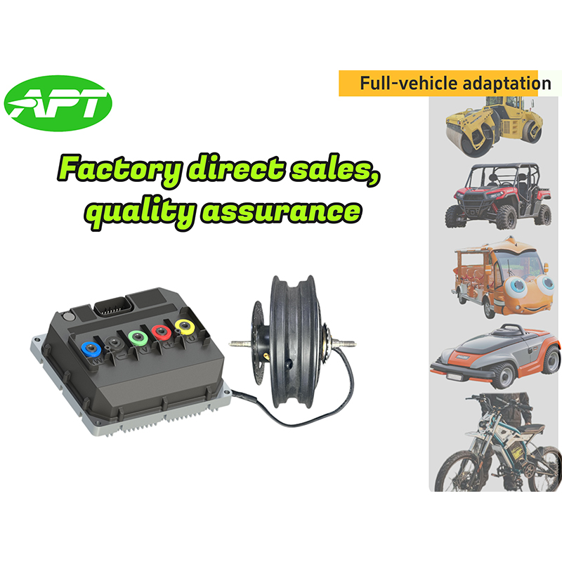 R5 Fast response Brushless DC Motor Controller Suppliers, Factory - Shanghai APTAPT is R5 Fast response Brushless DC Motor Controller Suppliers and Wholesale R5 Fast response Brushless DC Motor Controller Factory in C...View Product →
A marine outboard runs at a steady speed for hours, so efficiency and thermal stability matter more than transient response. An ATV or UTV sees sudden load changes on rough terrain, which favors a robust observer and generous current headroom. The table below summarizes the common trade-offs.
| Algorithm | Position Feedback | Torque Ripple | Low-Speed Behavior | Best-Fit Applications |
|---|---|---|---|---|
| Six-step commutation | Hall sensors | Moderate | Acceptable with sensors | Pumps, fans, low-cost traction |
| FOC with sensors | Hall or encoder | Very low | Excellent | Electric motorcycles, robots, marine |
| FOC sensorless (back-EMF) | Voltage and current | Low | Poor below minimum speed | E-bikes, high-speed drives |
| FOC sensorless (SMO/EKF) | Voltage and current | Low | Good, but tunable | ATV, UTV, industrial drives |
| High-frequency injection | Current response | Low | Excellent at standstill | Robots, servo-like duties |
| Scalar V/Hz | None | High | Not suitable | AC induction motors |
Treat the table as a starting point, not a verdict. A well-engineered controller can narrow many of these gaps because its current loop and observer are tuned together. That is why the controller vendor's experience with actual vehicle duty cycles matters as much as the algorithm name on the datasheet.
How the Algorithm Choice Affects Controller Selection
Because the algorithm lives in the embedded software, hardware and firmware must be designed together. MOSFET paralleling determines how evenly current divides between phases. Current sensing accuracy sets the floor for the FOC current loop. Gate drive strength affects switching losses and electromagnetic interference. Thermal design decides how long the controller can hold peak torque. A controller with good silicon but poorly tuned firmware will show torque ripple and noise; a controller with excellent firmware but weak current sensing will trip or derate. This is why so much engineering attention now goes to the role of software in modern motor control.
The same logic applies to the motor itself. Stator resistance, phase inductance, and the back-EMF constant define what the controller can and cannot do. A controller rated for 60 A will not make a poorly matched motor run efficiently, and aggressive FOC tuning can overheat a motor with low thermal mass. Requesting a validated motor-controller pairing is part of the purchasing process, not an afterthought.
On the hardware side, the T-series high-performance motor controllers pair wide-voltage FOC firmware with a power stage intended for e-motorcycles, e-ATVs, and e-outboards. They are an example of a design where the control algorithm and the inverter were developed in the same house, so the firmware knows the limits of the hardware.
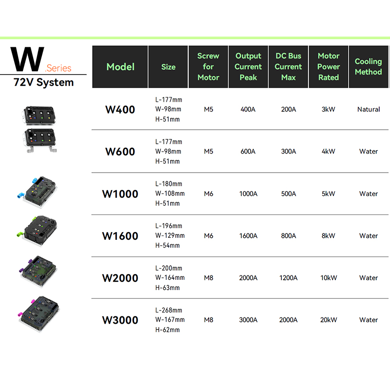 T Series High Performance Motor Controllers Suppliers, FactoryAPT - T300 T400 T500 T720 T1000 T1400 T1800 Permanent Magnet Synchronous Motor Controllers Factory, T Series High Performance Motor Contr...View Product →
Practical Evaluation Criteria for Motor Controllers
When you compare controllers, look behind the peak current number. The following points separate a controller that works on paper from one that works on the road.
- Confirm which algorithm the firmware actually runs. Some low-cost controllers advertise FOC but switch to six-step at high speed to hide computation limits.
- Check whether the FOC implementation is sensorless, Hall-based, or switchable. Sensorless reduces wiring but may struggle at very low speed without high-frequency injection.
- Ask how the current loop is tuned. Motors with different phase inductance require different gains, and automatic tuning saves hours during bring-up.
- Review overload behavior, including current limiting, thermal derating, and fault recovery. These details decide whether the vehicle stops safely or strands the rider.
- Consider acoustic noise. If the product is an electric motorcycle or a delivery robot that operates near people, noise is a selling point. The ultra-quiet brushless DC motor controller
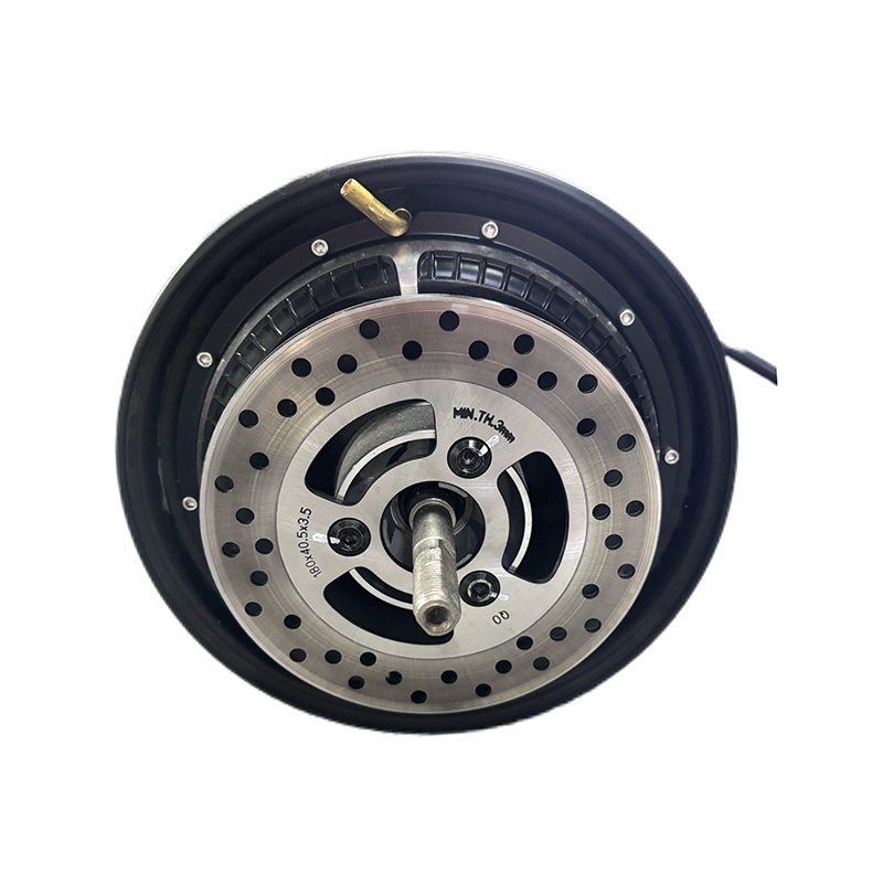 A6 Ultra-quiet Brushless DC Motor Controller Suppliers, Factory - Shanghai APT PAPT is A6 Ultra-quiet Brushless DC Motor Controller Suppliers and Wholesale A6 Ultra-quiet Brushless DC Motor Controller Factory in China...View Product → is a practical example of a sinusoidal-oriented design that keeps commutation noise low.
Motor control algorithms should not be chosen from a block diagram alone. Set the duty cycle, speed range, noise budget, and low-speed requirements of your vehicle first, then compare controllers against those targets. Six-step is perfectly adequate for a fan, FOC is the right starting point for most traction applications, and sensorless observers are a cost-saving tool when the speed range allows. The best controller is the one whose algorithm, power stage, and application support match your product's real operating profile.
NEXT:Torque Control Explained: A Practical Guide for BLDC Motor Controller Selection
Interested in cooperation or have questions?

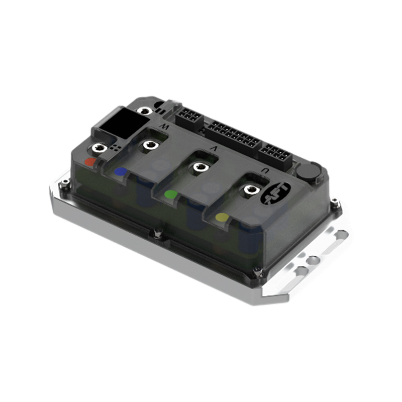
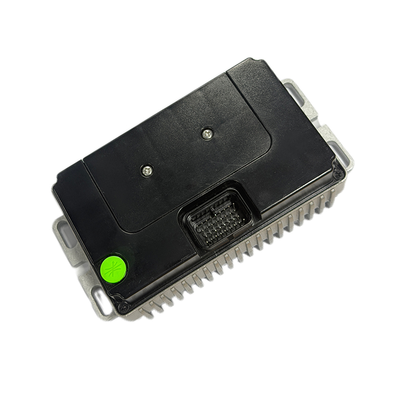
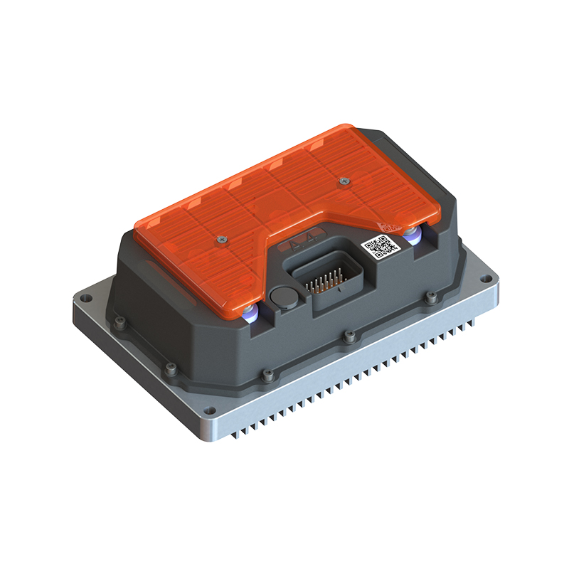
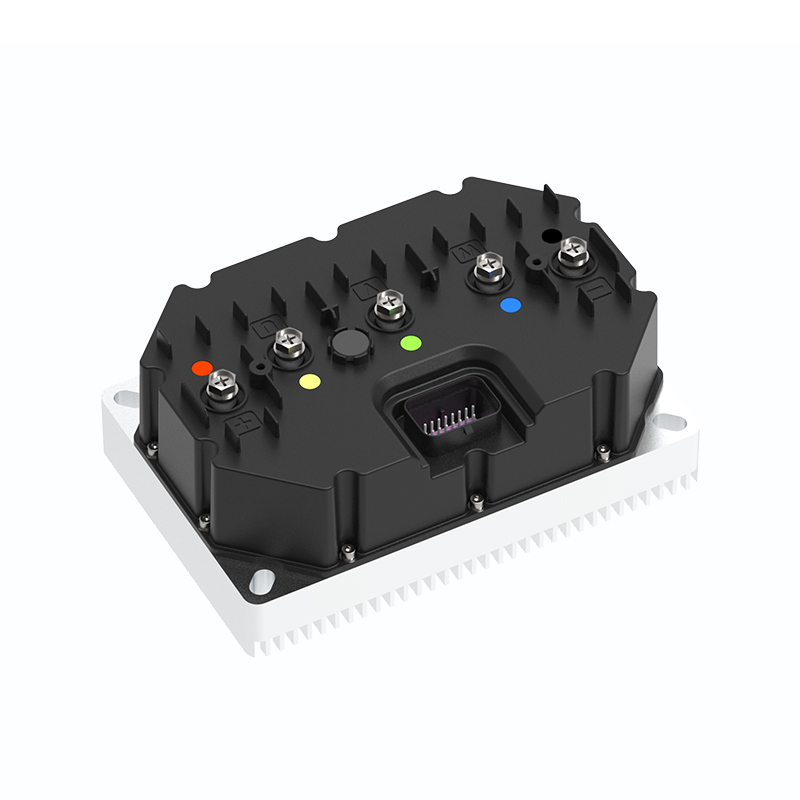

As Custom Permanent Magnet Synchronous Motor Controllers Manufacturers and Permanent Magnet Motor Controllers Suppliers in China, Focusing on the drive control of permanent magnet synchronous motors, we provide a safe and sufficient power source for the electrification of travel vehicles.
- [email protected]
- +86-170 9191 9800
- Room 123A, No. 1000 Ziyue Road, Minhang District, Shanghai, China
Copyright © Shanghai APT Power Technology Co., Ltd.All rights reserved

